19
mWing
Technical data
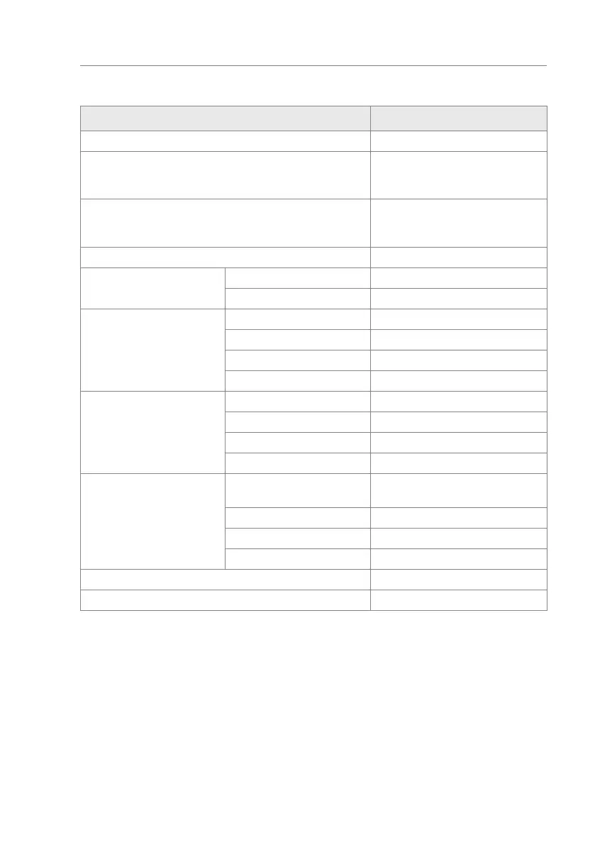
3.6 Control unit MGCplus
Designation Value
Power supply 24 V DC
Control unit max. 1 A max. 300 mA +
current consumption of the differ-
ent plug-in modules
Power consumption max. 24 W: Max. 7.2 W +
power consumption of the individu-
al plug-in modules
Control unit safety 1 A T
Output terminal 2 Output voltage 24 V DC
Max. output current 300 mA
Digital inputs Number 8
Input voltage 24 ± 10 % V DC
Input current < 10 mA per input
Max. cable length
1)
30 m
Digital outputs Number 4 (open collector)
Input voltage 24 ± 10 % V DC
Input current 100 mA
Max. cable length
1)
30 m
Relay outputs Number 3 closers + 3 changeovers,
isolated
Max. switching voltage 30 V AC / DC
Switching current 10 mA to 1 A
Max. cable length
1)
30 m
Display Graphics display, 128 x 65 Pixel
Number of slots for plug-in modules 5
1) Specification without optional overvoltage module. For line lengths exceeding 30 m, overvoltage
modules must be installed in front of the terminal clamps.
Table 7: Control unit MGCplus