63
mWing
Electrical connection
8.4.1 Connecting emergency opening contacts
ä Separate wiring diagram and document "Description control unit
MGCplus for mWing (Doc.ID: 5817,0033)".
Connect fire brigade switches, emergency opening contacts, etc. to the "Emer-
gency open" input. This input has the highest priority. The "Emergency open"
input function is superior to all other input functions. As long as +24 V DC are
present at this input, the pedestrian gate is in operation.
8.5 Installing and connecting customer-access control devices
You can install access-control devices in the following locations:
› At both ends of the housing
ä Separate wiring diagram and document "Description control unit
MGCplus for mWing (Doc.ID: 5817,0033)".
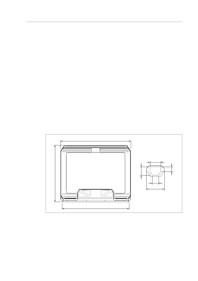
At both ends of the housing
Attach the access-control device to the cover with screws. Observe the installa-
tion dimensions.
1239.5
100
44
60
80
A
180
Fig. 32: Installation space for access-control device (dimensions in mm)
A Dimensions for customer's access-control device