6
6
7
Setting valve clearance
99
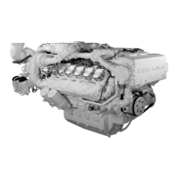
Fig. 5
Push feeler gauge between valve stem and rocker
arm. Loosen lock nut (17 mm) and turn adjusting
screw with screwdriver until feeler gauge can be
moved with slight resistance.
Tighten lock nut to the specified torque (see
“Service Data”) using screwdriver to prevent ad-
justing screw from turning. Check clearance again.
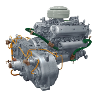
Fig. 6
Setting the valves can be considerably facilitated
by using the valve setting tool.
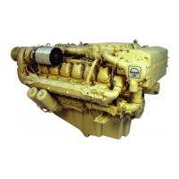
Fig. 7
Refit cylinder head covers with new gaskets.
 Loading...