9
10
11
Removing and installing valves
103
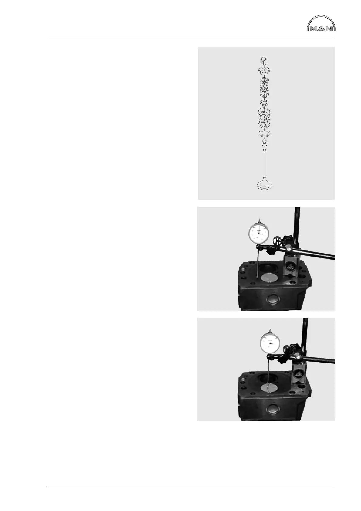
Fig. 8
Insert discs and valve springs.
The word ”TOP” facing upwards, the tight coils
facing downwards. Replace damaged or weak
springs.
Fit valve discs and tapered elements.
1 Valve
2 Valve stem seal (on the inlet valve only)
3 Washer
4 Outer valve spring
5 Washer
6 Inner valve spring
7 Spring retainer
8 Tapered element
Measuring valve recess
Figs. 9 and 10
Place dial gauge holder and dial gauge on cylinder
head so that the dial gauge tip contacts the
cylinder head and set dial gauge to “0”. Slew dial
gauge towards the valve disc and read off
retrusion. If necessary, change valve and/or valve
seat insert.
1
2
3
4
5
6
7
8
 Loading...