Engine lubrication diagram
20
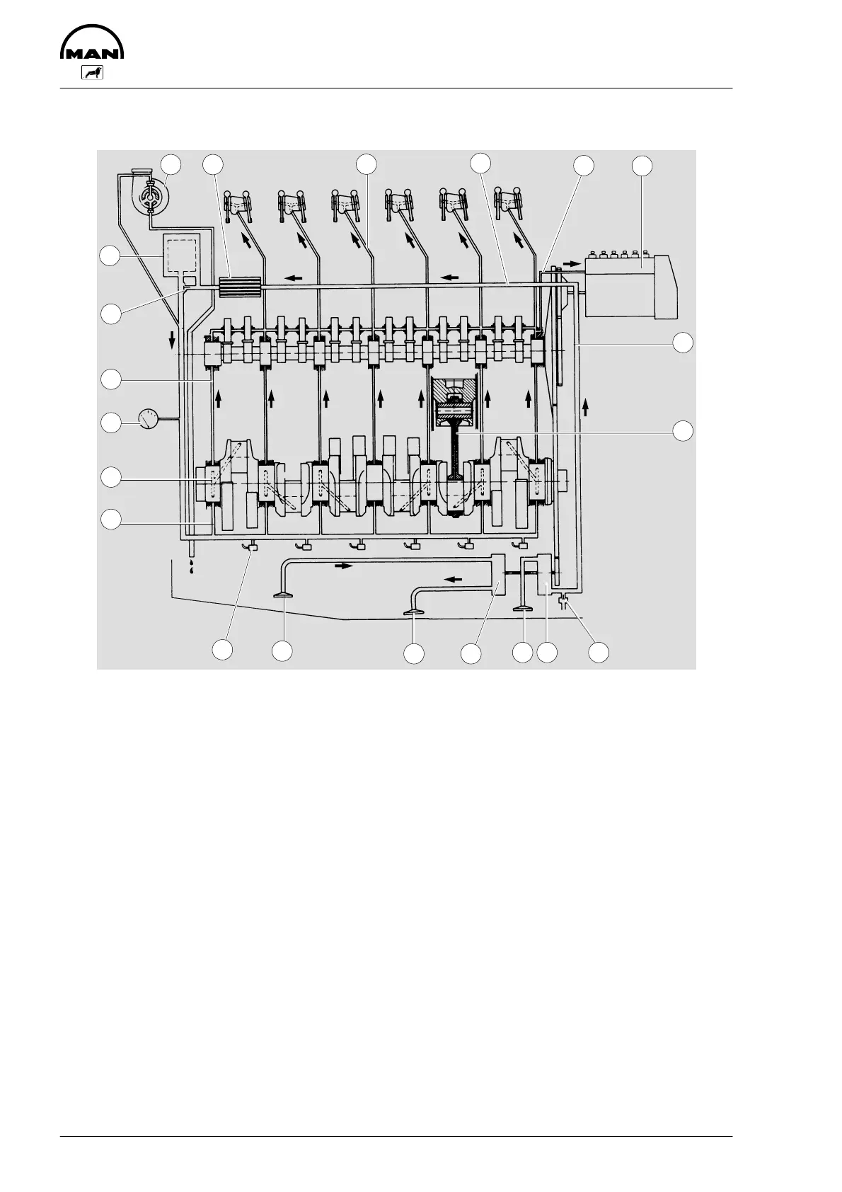
Schematic diagram of engine lubrication system
5
6
7
8910
1112
13
15
18
16
14
19
20
21 1
2
3
4
17
1 Oil cooler 11 Oil pump
2 Bore for rocker arm lubrication 12 Oil suction pipe
3 Bore for oilcooler 13 Oil suction pipe
4 Bore for injection pipe-lubrication 14 Spray nozzles for piston cooling
5 injection pump 15 Bore for main bearing lubrication
6 Bore for oil cooler 16 Bore for thrust bearing
7 Bore for gudgeon pin lubrication 17 Oil pressure sensor
8 Oil pressure relief valve 18 Bore for camshaft bearing lubrication
9 Oil pump 19 Bypass valve
10 Oil suction pipe 20 Oil filter
21 Turbocharger
 Loading...