9
10
11
Removing and installing valves
93
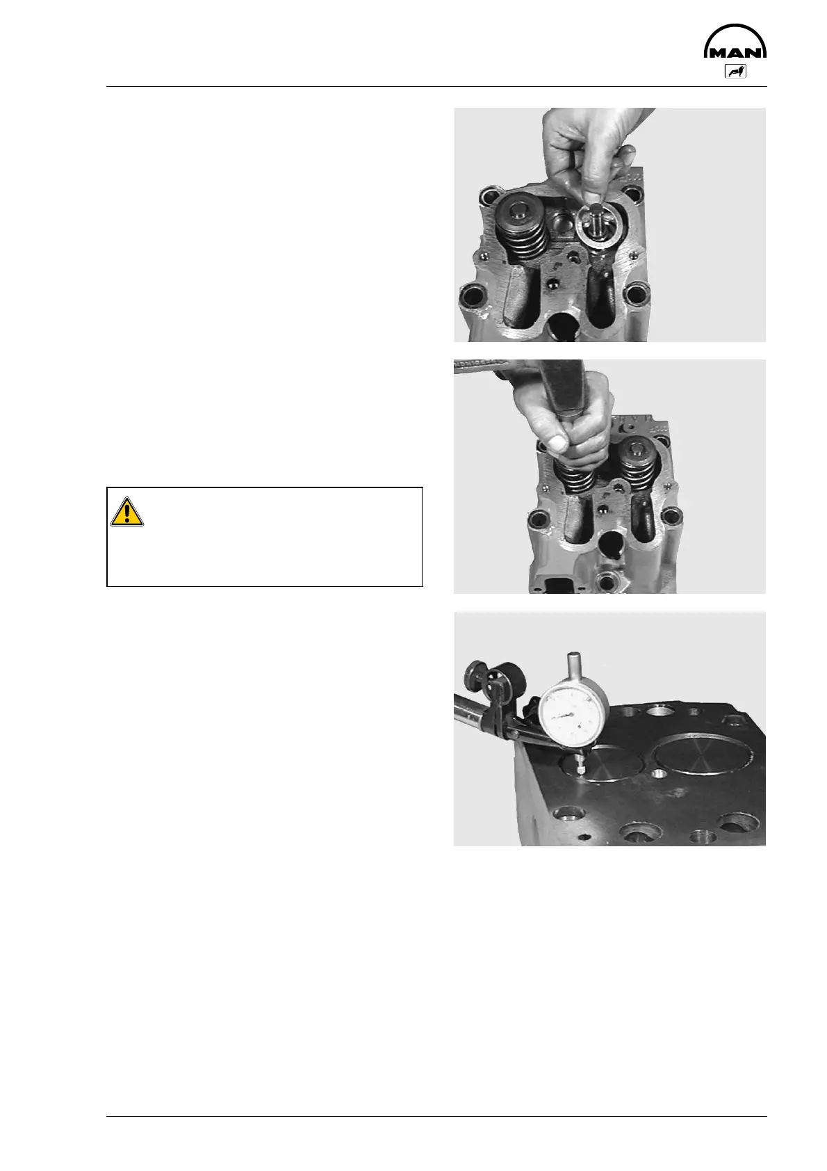
Fig. 9
Screw valve assembly lever on to cylinder head.
Insert the valve spring washers.
Insert discs and valve springs.
The word “TOP” facing upwards, the tight coils
facing downwards.
Replace damaged or weak springs.
Fig. 10
Compress the valve springs using assembly lever
and insert the valve cone pieces.
Use suitable tool to lightly knock back the valve
springs to ensure that the valve cone pieces sit
correctly.
Caution:
Ensure that the valve cone pieces sit cor-
rectly, since valve cone pieces which
jump out may cause considerable da-
mage.
Measuring valve recess
Fig. 11
D Place dial gauge holder and dial gauge on cylin-
der head
D Apply gauge tip under preload to cylinder head
D Set dial gauge to “0”
D Slew dial gauge towards the valve disc and
read off retrusion, if necessary exchanging
valve and valve seat insert
 Loading...