Tri-Loc Pre-Registration System
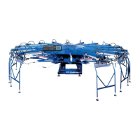
Once the Pin Bar has been attached to the Master Frame,
place a punched film on the Pin Strip and measure over
from the side stop block to find the image center. (See Fig.
3 “A”) and measure down from the top stop block to find
image start location. (See Fig. 3 “B”)
NOTE: DIMENSION “A” = Half of
frame width O.D. Example: 23”
wide = 11.5” - 25” wide = 12.5” - 26”
wide = 13.0” DIMENSION “B” =
6” for Gauntlet, Formula 5090 and
Challenger reverse print. 9” for
Challenger standard print and
Formula 5070.
Scribe these lines on the film and this will become your
Master Sheet for transferring dimensions to the layout table.
Ideally, the layout table should be a backlit unit to better
check actual film tolerances during the registration and
paste up process. Although the type of table used may vary,
it is important that the art table pin bar is positioned to
match the vertical centerline and image start position of that
on the Exposure Master Frame. (See Fig. 4)
If you are using a fully adjustable exposure frame, your lay-
out table should have 2 center lines, one for the 23” wide
frames, and one for the 25” wide frames. When pasting up
films to carrier sheets it is important to use the centerline
that corresponds with the frame size that will be used for
that job.
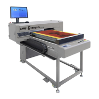
(ie: 23” frame = 11.5” centerline)When pasting up films, the
main or “trap color” should be positioned first and taped
securely to the pin mounted carrier sheet.(See Fig. 5)
It is recommended to tape up one color at a time to cut
down on the optical distortion that occurs when layering too
many films together.
The extra time and care taken at this point is critical to the
overall accuracy on the press.
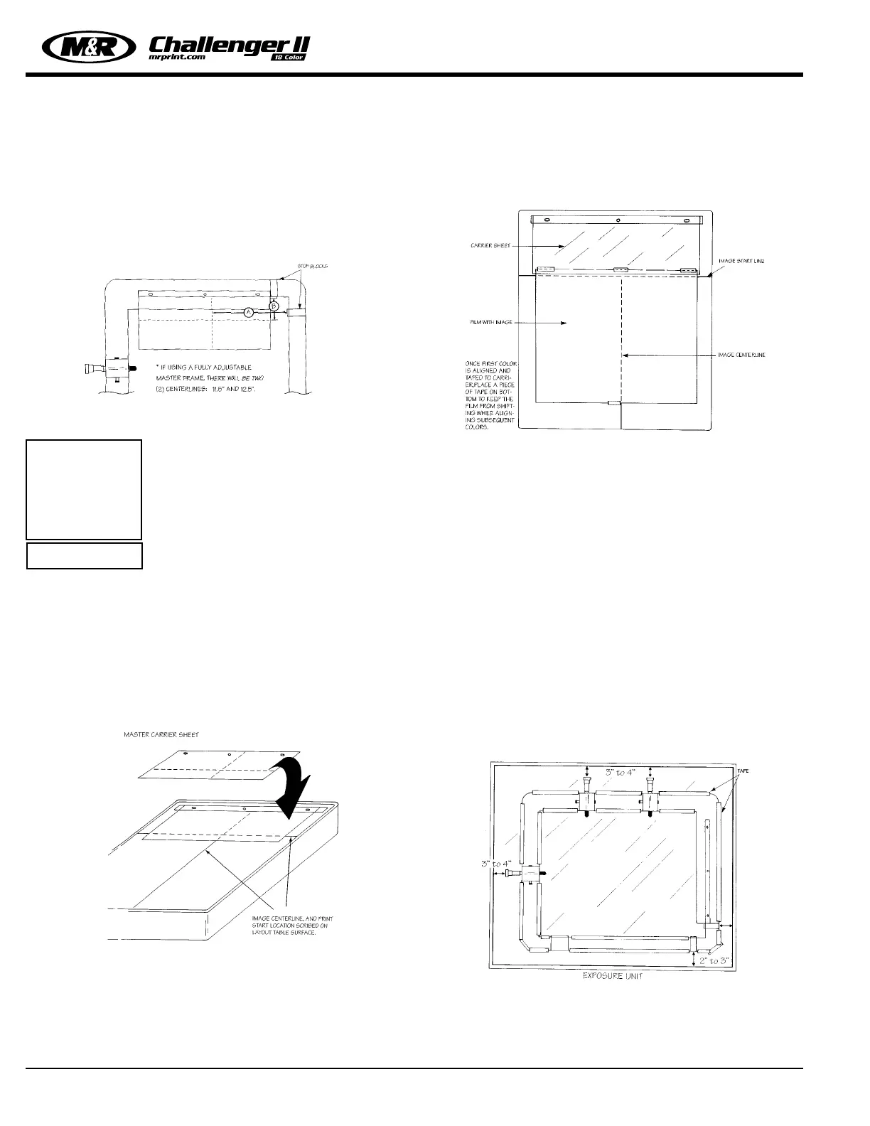
Exposure Unit Set-Up:
The exposure unit master frame is designed to be mounted
directly to the exposure unit. This mounting method can be
permanent or removable. It is recommended however, that
which ever exposure unit you elect to use with the Tri-Loc
system, that this exposure unit be dedicated to the Tri-Loc
system for all future set-ups. The master frame may be
attached to the glass using a heavy grade tape such as duct
tape. Typical one up semi-permanent installation showing
stop blocks towards the operator for ease of loading and
confirming stop block contact. (See Fig. 6)
M&R Printing Equipment, Inc. - Glen Ellyn, Illinois
16
i
IMPORTANT!
Figure 4
Figure 5
Figure 6
Figure 3
 Loading...