M&R Printing Equipment, Inc. - Glen Ellyn, Illinois
25
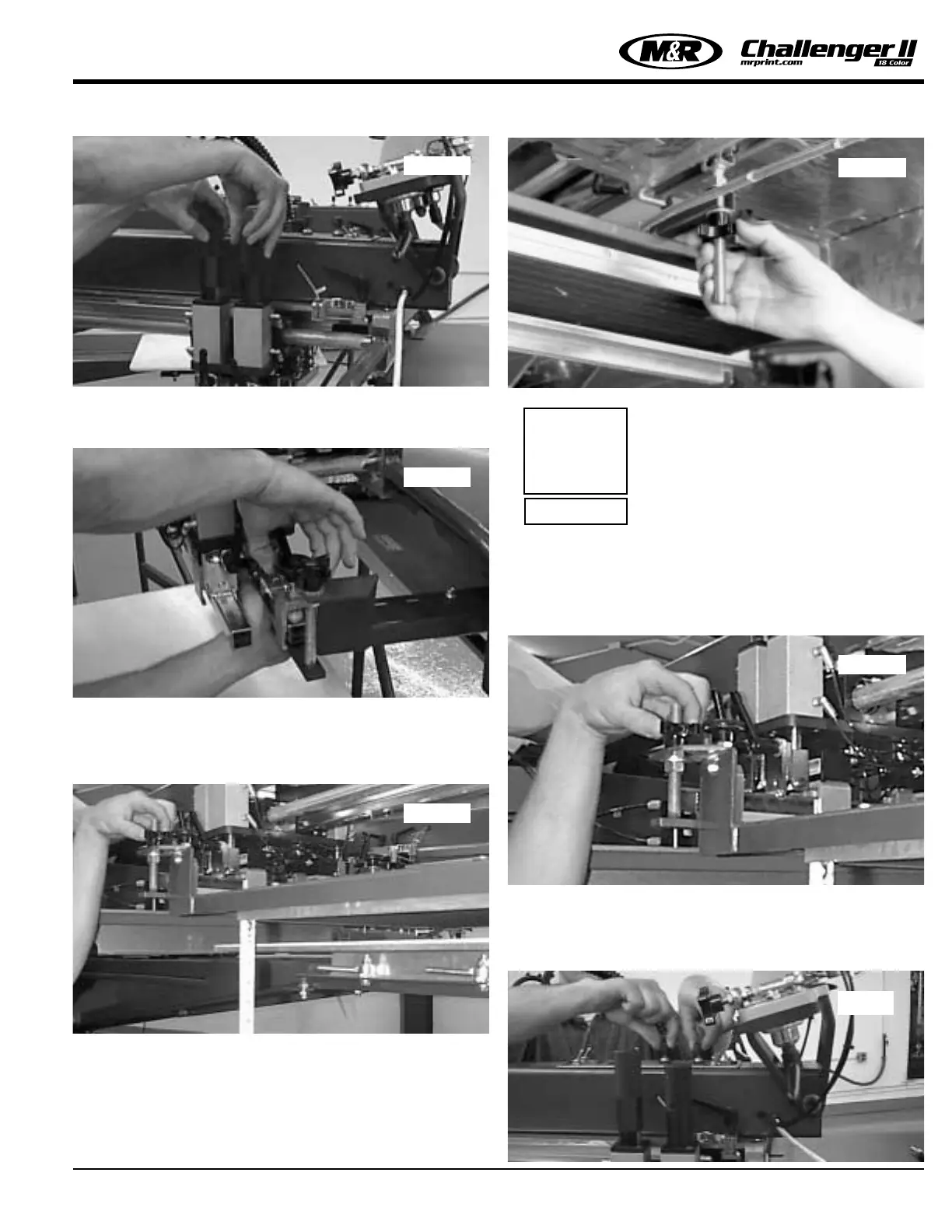
7. Install the flash panel mounting bracket on the mounting
bar and secure with two squeegee clamps (manual) (See
Fig. 8)
The height of the heat panel may be adjusted by using the
black plastic cross knobs, which are threaded onto the
threaded support rod on top of the flash panel mounting
bracket. (See Fig. 9)
8. To adjust the infrared panel at the rear for proper level,
adjust the black plastic cross knob located at the rearuni-
strut support channel under the infrared panels insulated
cover guard. (See Fig. 9A top right)
NOTE: Check to be sure all bolts and
nuts are securely tightened.
9. Adjust both the front and rear threaded support rods so
that the dimensions from the top of the printing pallet to the
bottom of the infrared heat panel is 3/4” (1.9 cm) to 1-1/2”
(3.8 cm) at all four corners. Make this adjustment while the
index table is in the fully raised position. (See Fig. 10)
10. Set the inboard speed and the outboard speed of the
infrared panel by adjusting the squeegee and flood bar
speed controls located on the top of the print station. (See
Fig. 11)
Omni/Uni Flash Operation
Fig. 7
Fig. 8
Fig. 9
Fig. 9A
i
IMPORTANT!
Fig. 10
Fig. 11
 Loading...