Operator Controls
M&R Printing Equipment, Inc. - Glen Ellyn, Illinois
36
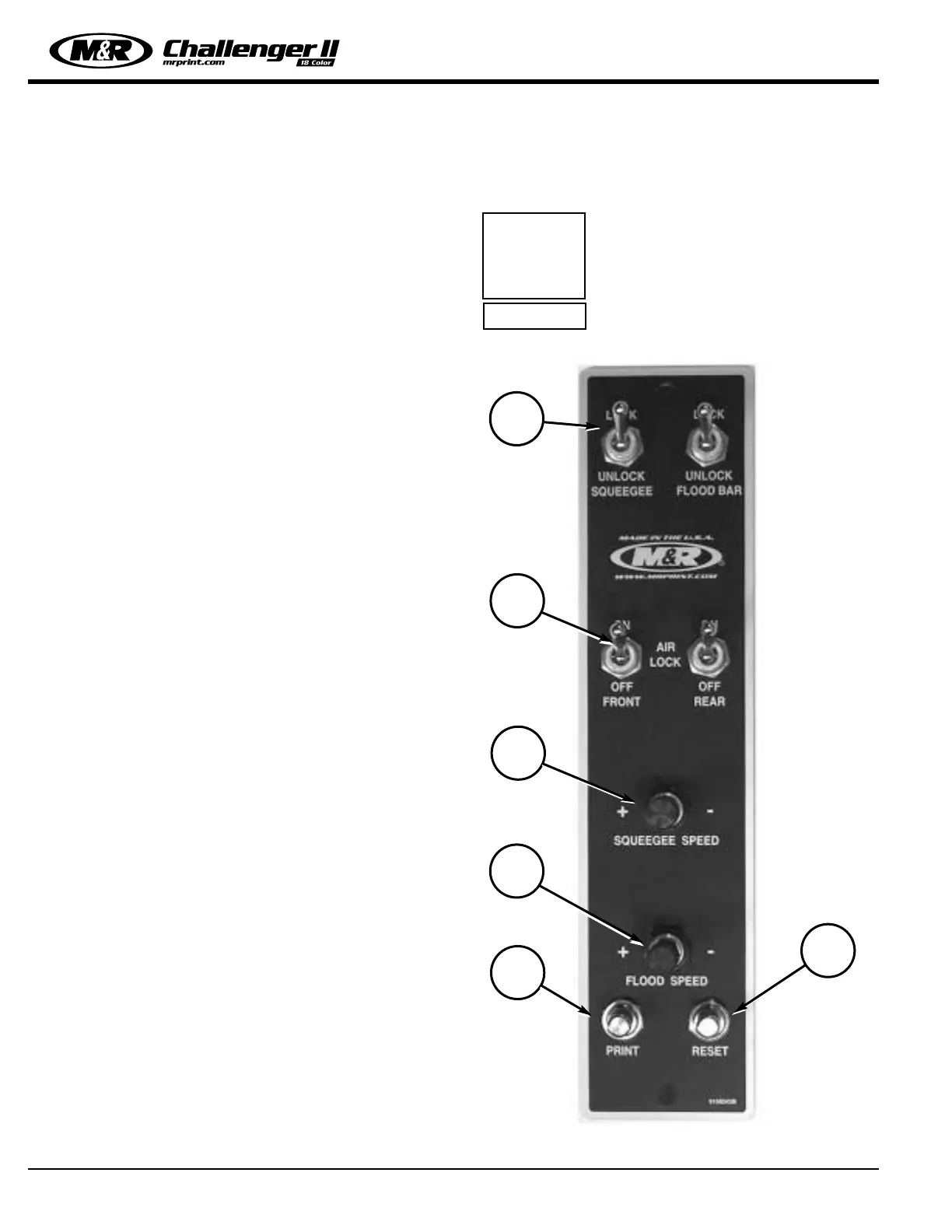
Individual Print Station Controls:
Each of the print stations used on the M&R Challenger
Series II includes individual controls for adjustment of flood
stroke speed, print stroke speed, independent print start,
On/Off switches for pneumatic screen frame clamps and, if
ordered as an option, squeegee/flood bar pneumatic
clamps, and “Reset” push button.
1. Squeegee/Flood Bar Pneumatic Locking Clamps
(Optional):
Located at the top of the print station control panel, these
toggle switches are used to lock the squeegee and flood
bar to their respective mounting bars. To lock the squeegee
or flood bar to the print station carriage mounting bars, sim-
ply position the squeegee or flood bar on the mounting bar
and place the toggle switch in the “On” lock position (up).
2. Pneumatic Screen Frame Locks:
Situated just below the pneumatic squeegee/flood bar lock-
ing clamps controls are the pneumatic screen frame locking
clamp control switches. The toggle switch on the left acti-
vates the front screen frame clamps, while the right toggle
switch activates the rear screen frame locking clamps. To
lock the screen frame into the screen frame holder assem-
bly, simply locate the screen frame in position and place the
toggle switches in the “On” (up) position. The pneumatic
cylinders (front & rear) will securely lock the screen frame
into the screen holder assembly. To release the screen
frame, simply move the toggle switches to the “Off” position
and remove the screen frame from the holder assembly.
3. Squeegee Speed Adjustment:
(Pneumatic Heads Only)
The squeegee speed may be independently adjusted by use
of this convenient control knob. To increase the squeegee
speed, turn the control knob counterclockwise. To decrease
the squeegee speed, turn the control knob clockwise.
4. Flood Bar Speed Adjustment:
(Pneumatic Heads Only)
The flood bar speed may be independently adjusted by use
of this convenient control knob. To increase the flood bar
speed, turn the control knob counterclockwise. To decrease
the flood bar speed, turn the control knob clockwise.
5. Independent Print Push Button:
As described in the Main Control Panel section, this push
button is used to cycle the individual print station manually.
The “Print” push button is also used during screen frame
set-up to check for proper screen placement during regis-
tration adjustments. To operate, place the “Single/Double”
toggle switch for the particular print station on the Main
Control Panel in the middle, or “Off” position. Now press
the “Print” push button on the print station control panel.
The index table will raise so that screen placement and reg-
istration may be checked.
To lower the index table, press the green “Reset” push but-
ton located just to the right of the “Print” push button on
the Print Station control panel.
NOTE: The “Single/Double” toggle
switch on the Main Control Panel must
be selected for either “Single” or
“Double” operation in order for the
print station to operate.
i
IMPORTANT!
1
2
3
5
4
6
 Loading...