G3 - FRONT HEADLAMPS
G3 - FRONT HEADLAMPS
ADJUSTADJUST
RECOMMENDED SETTINGRECOMMENDED SETTING
(as per standard ECE-76/756 76/761 ECE20)(as per standard ECE-76/756 76/761 ECE20)
Set to - 2Set to - 2 % of the dipped beam % of the dipped beam in relation to the horizontal line oin relation to the horizontal line off
the headlamp.the headlamp.
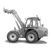
ADJUSTING PROCEDUREADJUSTING PROCEDURE
-- Place the lift Place the lift truck unloaded and truck unloaded and in the transin the transporport position t position andand
perpendicular to a white wall on flat, level ground (fig. G3).perpendicular to a white wall on flat, level ground (fig. G3).
-- Check the tire pressures Check the tire pressures (see: 2 - (see: 2 - DESCRIPTION: FRONT DESCRIPTION: FRONT AND REARAND REAR
TIRES).TIRES).
- Put the gearshift lever into neutral.- Put the gearshift lever into neutral.
Calculating the height of the dipped Calculating the height of the dipped beam (h2)beam (h2)
• h1 =• h1 = Height of the Height of the dipped beam in relation dipped beam in relation to the ground.to the ground.
• h2 =• h2 = Height of thHeight of the adjuste adjusted beam.ed beam.
• l =• l = Distance between the Distance between the dipped beam and dipped beam and the white wall.the white wall.
G4 - LIFT TRUCKG4 - LIFT TRUCK
TOWTOW
Do not tow the lift truck at more than 25 km/h.Do not tow the lift truck at more than 25 km/h.
-- Put the forward/reverse selector and the Put the forward/reverse selector and the gear shift in ngear shift in neutral.eutral.
- Release the hand brake.- Release the hand brake.
- Put the warning lights on.- Put the warning lights on.
-- If the I.C. engine is not running there will be no steering or braking assistance. If the I.C. engine is not running there will be no steering or braking assistance. Operate the steering and pedal slowly avoidingOperate the steering and pedal slowly avoiding
sudden jerky movements.sudden jerky movements.
G5 - LIFT TRUCKG5 - LIFT TRUCK
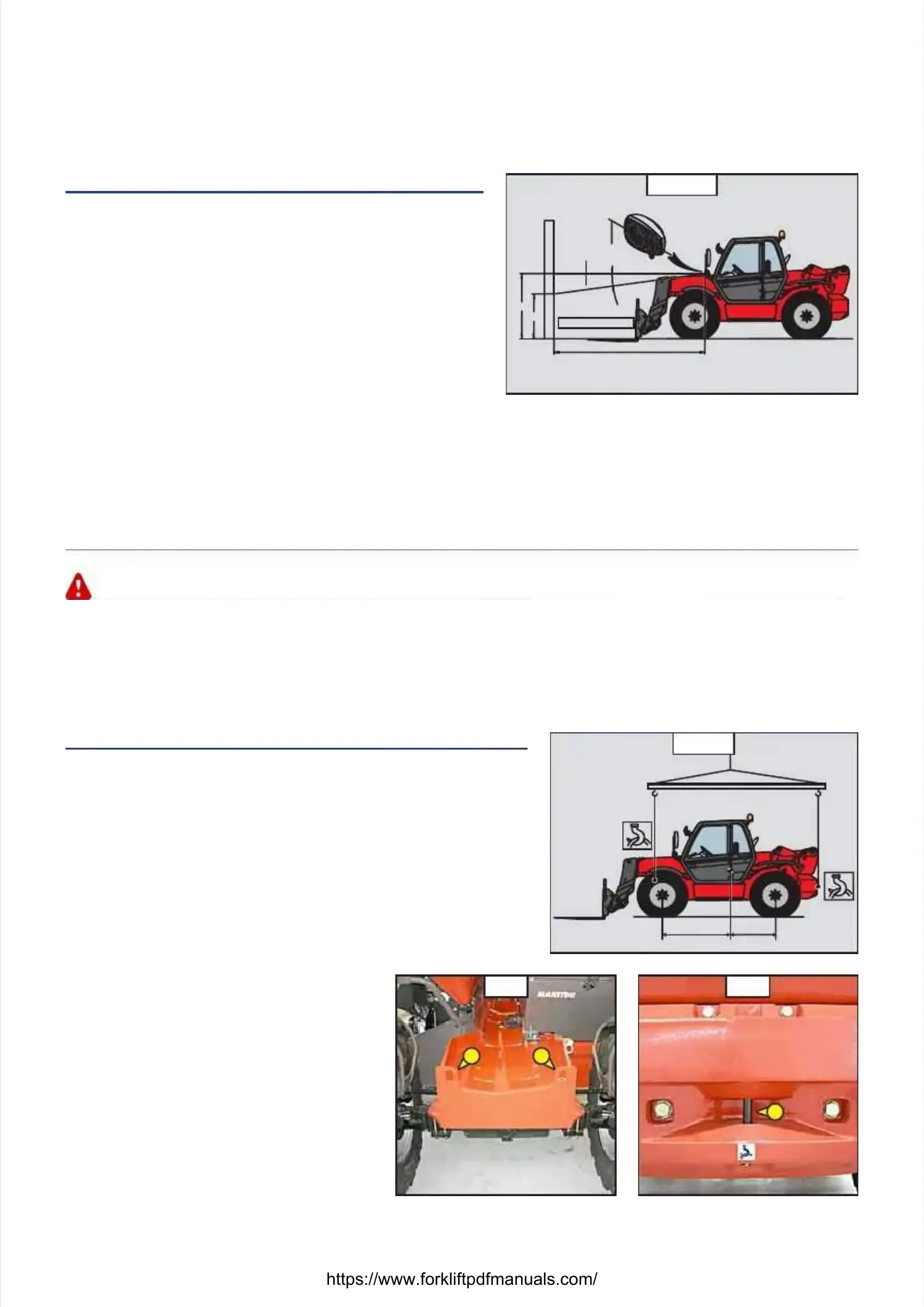
SLINGSLING
-- TTake into account the position of the lift truck centre of gravity for liftingake into account the position of the lift truck centre of gravity for lifting
(fig. G5/1).(fig. G5/1).
A = 1560 mm B A = 1560 mm B = 1210 mm ML= 1210 mm MLTT 845 120 LSU845 120 LSU Série 3-E3Série 3-E3
A = 1510 mm B A = 1510 mm B = 1260 mm ML= 1260 mm MLTT 940 L 120 LSU940 L 120 LSU Série 3-E3Série 3-E3
-- Place the hooks in the fastPlace the hooks in the fastening points provided (fig. G5/2 and G5/ening points provided (fig. G5/2 and G5/3).3).
GG55//2 2 GG55//33
+%+%
-%-%
ll
h1h1
h2h2
--
22
%%
h2 = h1 - (l x 2 / 100)h2 = h1 - (l x 2 / 100)
h1h1
G3
G3
A A BB
G5/1G5/1
 Loading...