1-15
1-15
D - TRANSVERSE ATTITUDE OF THE LIFT TRUCKD - TRANSVERSE ATTITUDE OF THE LIFT TRUCK
Depending on the model of lift truckDepending on the model of lift truck
The transverse attitude is the transverse slope of the chassis with respect to theThe transverse attitude is the transverse slope of the chassis with respect to the
horizontal.horizontal.
Raising the jib reduces the liRaising the jib reduces the lift truck’s lateral stability. The transverse attitude must be setft truck’s lateral stability. The transverse attitude must be set
with the jib in down position as follows:with the jib in down position as follows:
1 - LIFT TRUCK WITHOUT SLOPE CORRECTOR USED ON 1 - LIFT TRUCK WITHOUT SLOPE CORRECTOR USED ON TYRESTYRES
-- Position the lift truck so that the Position the lift truck so that the bubble in the level is bebubble in the level is between the two lines (stween the two lines (see: 2 -ee: 2 -
DESCRIPTION: INSTRUMENTS AND CONTROLS).DESCRIPTION: INSTRUMENTS AND CONTROLS).
2 - LIFT TRUCK WITH SLOPE CORRECTOR USED ON 2 - LIFT TRUCK WITH SLOPE CORRECTOR USED ON TYRESTYRES
-- Correct the slope using the Correct the slope using the hydraulic control and verify hydraulic control and verify the horizontality via the the horizontality via the level. Thelevel. The
bubble in the level bubble in the level must be between the two lines must be between the two lines (see: 2 - DESCRIPTION: INSTRUMENTS(see: 2 - DESCRIPTION: INSTRUMENTS
AND CONTROLS).AND CONTROLS).
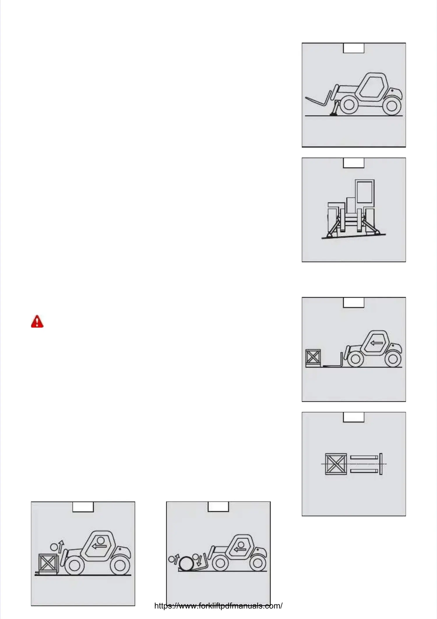
3 - LIFT 3 - LIFT TRUCK USED ON STABILIZERSTRUCK USED ON STABILIZERS
- Set the two stabilizers on the gr- Set the two stabilizers on the ground and raise the two front wheels of the ound and raise the two front wheels of the lift truck (fig. lift truck (fig. D1).D1).
-- Correct the slope using the sCorrect the slope using the stabilizers (fig. D2) and tabilizers (fig. D2) and make sure the truck is horizontalmake sure the truck is horizontal
by checking the level. The bubble of the level must be between the two lines (see: 2by checking the level. The bubble of the level must be between the two lines (see: 2
- DESCRIPTION: INSTRUMENTS AND CONTROLS). In this position, the two front wheels- DESCRIPTION: INSTRUMENTS AND CONTROLS). In this position, the two front wheels
must be off the ground.must be off the ground.
E - TAKING UP A LOAD ON THE GROUNDE - TAKING UP A LOAD ON THE GROUND
-- Approach the lift truck perpendicular to the load, with Approach the lift truck perpendicular to the load, with the jib retracted and the forks the jib retracted and the forks in a horizontal position (fig. E1)in a horizontal position (fig. E1)..
-- Adjust the fork spread and ceAdjust the fork spread and centering in connection with the load (fig. ntering in connection with the load (fig. E2) (optional solutionsE2) (optional solutions
exist, consult your dealer).exist, consult your dealer).
- Never lift a load with a single fork.- Never lift a load with a single fork.
Beware of the risks of trapping or squashing limbs when manually adjusting the Beware of the risks of trapping or squashing limbs when manually adjusting the forks.forks.
-- Move the lift truck forMove the lift truck forward slowly (1) and bring the forks tward slowly (1) and bring the forks to stop in front of the load (fig.o stop in front of the load (fig.
E3), if necessary, slightly lift the jib (2) while taking up the load.E3), if necessary, slightly lift the jib (2) while taking up the load.
- Bring the load into the transport position.- Bring the load into the transport position.
-- Tilt the load far enough bacTilt the load far enough backwards to ensure stability (loss kwards to ensure stability (loss of load on braking or goingof load on braking or going
downhill).downhill).
FOR A NON-PALLETIZED LOADFOR A NON-PALLETIZED LOAD
-- Tilt the carriage (1) Tilt the carriage (1) forforwards and move wards and move the lift truck slowly the lift truck slowly forwarforwards (2), ds (2), to insert the forkto insert the fork
under the load (fig. E4) (block the load if necessary).under the load (fig. E4) (block the load if necessary).
-- Continue to move the lift Continue to move the lift truck fortruck for wards (2) tilting the carriage (3) (wards (2) tilting the carriage (3) (fig. E4) backwards tofig. E4) backwards to
position the load on the position the load on the forks and check the load’s longitudinal and forks and check the load’s longitudinal and lateral stability.lateral stability.
D1D1
D2D2
E1E1
E2E2
11
22
E3E3
11
22
33
E4E4
 Loading...