G - OCCASIONAL MAINTENANCE
G - OCCASIONAL MAINTENANCE
G1 - WHEELG1 - WHEEL
CHANGECHANGE
In the event of a In the event of a wheel being changed on the public highway, make sure of the following points:wheel being changed on the public highway, make sure of the following points:
For this operation, we advise you to use the hydraulic For this operation, we advise you to use the hydraulic jack MANITOU reference 505507 andjack MANITOU reference 505507 and
the safety support MANITOU reference 554772.the safety support MANITOU reference 554772.
- Stop the lift truck, if possible on even and hard ground.- Stop the lift truck, if possible on even and hard ground.
-- To pass on stop of lift truck (see: 1 - OPERATITo pass on stop of lift truck (see: 1 - OPERATING AND SAFETY INSTRUCTIONS: DRIVINGNG AND SAFETY INSTRUCTIONS: DRIVING
INSTRUCTIONS UNLADEN AND LADEN).INSTRUCTIONS UNLADEN AND LADEN).
- Put the warning lights on.- Put the warning lights on.
- Immobilise the lift truck in both directions on the axle opposite to the wheel to be changed.- Immobilise the lift truck in both directions on the axle opposite to the wheel to be changed.
-- Unlock the nuts Unlock the nuts of the wheel of the wheel to be changed.to be changed.
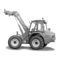
-- Place the jack under the flared axle tube, as near as possible to the whePlace the jack under the flared axle tube, as near as possible to the wheel and adjust theel and adjust the
jack 1 (fig. G1).jack 1 (fig. G1).
-- Lift the wheel until it comes off the ground and put in place Lift the wheel until it comes off the ground and put in place the safety support 2 under the axle (fig. G1).the safety support 2 under the axle (fig. G1).
- Completely unscrew the wheel nuts and - Completely unscrew the wheel nuts and remove them.remove them.
- Free the wheel by reciprocating movements and roll it to the side.- Free the wheel by reciprocating movements and roll it to the side.
- Slip the new wheel on the wheel hub.- Slip the new wheel on the wheel hub.
- Refit the nuts by hand, if necessary grease them.- Refit the nuts by hand, if necessary grease them.
- Remove the safety support and lower the lift truck with the jack.- Remove the safety support and lower the lift truck with the jack.
-- Tighten the wheel nuts with a torque wrench (see: 3 - MAINTENANCE: A - DAILY OR EVERY 10 HOURS SERVICE for tighteningTighten the wheel nuts with a torque wrench (see: 3 - MAINTENANCE: A - DAILY OR EVERY 10 HOURS SERVICE for tightening
torque).torque).
G2 - PARKING BRAKEG2 - PARKING BRAKE
UNBLOCKINGUNBLOCKING
This procedure is to be performed in the event of parking brakeThis procedure is to be performed in the event of parking brake
malfunction.malfunction.
If the lift truck is not on a horizontal grIf the lift truck is not on a horizontal ground, to fix so that it does notound, to fix so that it does not
descend the slope.descend the slope.
Do not tow the lift truck at more than 25 km/h.Do not tow the lift truck at more than 25 km/h.
-- Put the forward/reverse selector and the Put the forward/reverse selector and the gear shift in ngear shift in neutral.eutral.
- Put the warning lights on.- Put the warning lights on.
MANUALLY UNBLOCKING THE PARKING BRAKEMANUALLY UNBLOCKING THE PARKING BRAKE
-- First perforFirst perfor m this operation on the left-hand m this operation on the left-hand side (fig.G2/1) of the fside (fig.G2/1) of the front axle, then on theront axle, then on the
right-hand side (fig.G2/1).right-hand side (fig.G2/1).
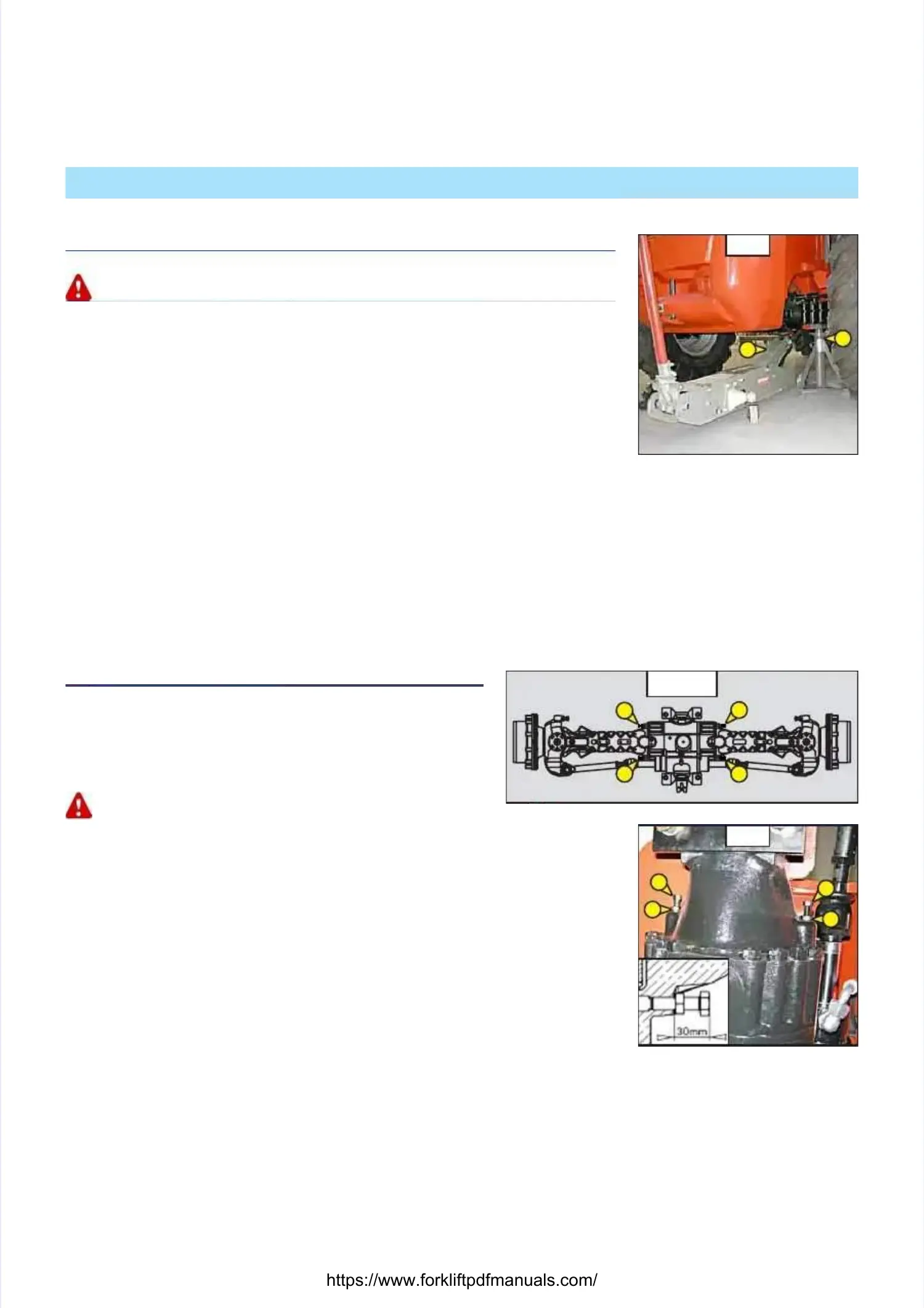
- Unscrew locknuts 1 (fig. G2/2) by - Unscrew locknuts 1 (fig. G2/2) by approximately 8 mm.approximately 8 mm.
-- Alternately tighten the screws 2 (fig. G2/2) Alternately tighten the screws 2 (fig. G2/2) by a 1/4 turn at a time up to a by a 1/4 turn at a time up to a maximum of 1maximum of 1
turn in order to free the brake discs.turn in order to free the brake discs.
-- If the I.C. engine is nIf the I.C. engine is not running there will be no steering or braking assistance. Operot running there will be no steering or braking assistance. Operateate
the steering and pedal slowly avoiding the steering and pedal slowly avoiding sudden jerky movements.sudden jerky movements.
- Once this operation is completed, adjust the - Once this operation is completed, adjust the parking brake.parking brake.
ADJUSTING THE PARKING BRAKEADJUSTING THE PARKING BRAKE
-- First perforFirst perfor m this operation on the left-hand m this operation on the left-hand side (fig.G2/1) of the fside (fig.G2/1) of the front axle, then on theront axle, then on the
right-hand side (fig.G2/1).right-hand side (fig.G2/1).
- Completely unscrew screws 2 (fig. G2/2) by alternately unscrewing them a 1/4 turn at a time.- Completely unscrew screws 2 (fig. G2/2) by alternately unscrewing them a 1/4 turn at a time.
- Grease the threads with a silicone lubricant (MANITOU reference: 479292).- Grease the threads with a silicone lubricant (MANITOU reference: 479292).
- Retighten the screws 2 (fig. G2/2) to - Retighten the screws 2 (fig. G2/2) to obtain a dimension of 30 obtain a dimension of 30 mm (fig. G2/2).mm (fig. G2/2).
- Lock the locknuts 1 (fig. G2/2) while holding the screw 2 (fig. G2/2) in position.- Lock the locknuts 1 (fig. G2/2) while holding the screw 2 (fig. G2/2) in position.
G2/2G2/2
22
22
11
11
G2/1G2/1
G1G1
11
22
 Loading...