Home
Manitowoc
Construction Equipment
999
Manitowoc 999 Service And Maintenance Manual
4
of 1
of 1 rating
298 pages
Give review
Manual
Specs
To Next Page
To Next Page
To Previous Page
To Previous Page
Loading...
Reference
Only
Manitowoc
Published 05-16-17, Control # 233-03
2-5
999 SERVICE/MAINTENANCE MANUAL
HYDRAULIC SYSTEM
2
OPEN
CLOSE
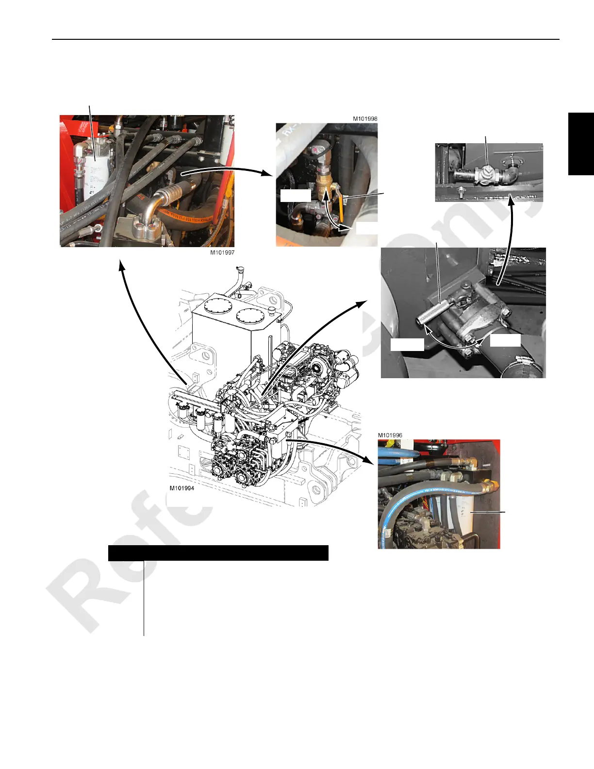
FIGURE 2-1 continued
Item
Description
14
Auxiliary Drum Hydraulic Oil
Filter
15
Charge Filter Shut-Of
f V
alve
16
Hydraulic T
ank Shu
t-Off V
alve
(suction tube)
17
Hydraulic Oil Charge Filt
ers (3)
18
Hydraulic T
ank Drain V
alve
14
15
OPEN
CLOSE
16
17
Bottom of Hydraulic T
ank Accessibl
e from
Under Rear of Rot
ating Bed
18
84
86
Table of Contents
Table of Contents
5
Continuous Innovation
13
Safety Messages
13
Safety Alert Symbol
13
Signal Words
13
Safe Maintenance Practices
14
Maintenance Instructions
14
Environmental Protection
15
Crane Operation
16
Operating System
16
Hydraulic Components
16
Hydraulic Tank
16
Shut-Off Valve
17
Supercharge Filter Manifold
17
Return Manifolds
17
Thermal Bypass Valve
17
Hydraulic Pumps
17
Main Pressure Monitoring
18
Accessory System Pressure
18
Basic Operation
18
Charge Pressure
18
Hydraulic Motors
18
Engine Controls
20
Epic Programmable Controller
21
Standard Mode
22
Other Crane Modes
22
Electrical Power to 999 Operator Cab
23
Pressure Senders and Encoders
24
System Faults
25
Operating Faults and Limit Switches
26
Brake and Drum Pawl Application/Release
26
Swing System Operation
28
Swing Brake and Swing Lock
28
Swing Right or Left
28
Swing Holding Brake Switch
29
Travel System Operation
30
Travel Brakes
30
Travel Forward and Reverse
30
Travel Speed-High/Low Operation
30
Travel Detent Selector
31
Boom Hoist System Operation
33
Boom Hoist Brake and Pawl Switch
33
Boom Hoist Raise
34
Boom Stop Cylinders
35
Boom Hoist Lower
35
Front/Rear Drum System
38
Load Drum Brake and Pawl Switch
39
Load Drum Hoisting
39
Load Drum Lowering
40
Luffing Jib Operation (Optional)
42
Free Fall Mode (Optional)
43
Drum Brake and Pawl Switch
43
Free Fall Brake/Clutch Operation
43
Free Fall Hoisting
44
Free Fall Lowering
45
Auxiliary Drum System (Optional)
49
Auxiliary Drum Brake and Pawl Switch
50
Auxiliary Drum Raise
50
Auxiliary Drum Lower
51
Crane Setup Systems
54
Gantry System
55
Gantry Cylinders Raise
55
Gantry Cylinders Lower
59
Mast System
62
Mast Cylinders Raise
64
Mast Cylinders Lower
65
Boom Hinge Pins
68
Carbody Jacking System
70
Carbody Jacking Cylinder Raise
71
Carbody Jacking Cylinder Lower
71
Left and Right Crawler Pin-Pusher Cylinders
73
Right Crawler Pin-Pusher Cylinders Engage
73
Right Crawler Pin-Pusher Cylinders Disengage
73
Counterweight Pins
75
Hydraulic Solenoid Valve Identification
77
Inspecting Hydraulic Hoses
81
Every Month or 200 Hours
81
Degradation Due to Extreme Environment
81
Hydraulic System Maintenance
82
Safety
82
Storing and Handling Oil
82
Storing and Handling Parts
82
Inspecting System
82
Replacing Filter Elements
86
Changing Oil
86
Tightening Hydraulic Connections
87
Pipe Thread Connection
87
SAE Straight Thread Connection
88
ORS Connection
89
Split Flange Connection
90
SAE Flare Connection
91
Hydraulic System Calibration
92
Accessing Calibration Screens
92
Calibration Procedures
92
Pressure Sender
92
Charge Pressure
93
Control System
94
Pump Pressure
95
Pressure Sender Replacement
98
Pump Components
100
Pump Identification
100
Pump and Motor Port Identification
101
Disc Brake Operational Test
103
Operational Test
103
Shop Procedures
103
Initial Oil Fill
104
Accessory System Checks and Adjustments
106
High Pressure Accessory Systems
106
Low Pressure Accessory Manifold
106
Travel Handle and Speed Check
107
Operating Drum Speed Checks
107
Inspect Electrical Components
111
Every Month or 200 Hours
111
Degradation Due to Severe Environment
111
Circuit Breaker and Fuse ID
112
Test Voltages
118
Controller Board Layout
118
Test Voltage Abbreviations
118
Pin Identification
119
Wire Identification
123
Description Identification
127
Controller Board Identification
131
Master Node Pin Identification
136
Display Readings
138
Operating Conditions
138
Operating Limits
138
System Faults
139
Selecting Display Language
139
Crane Diagnostics
144
Drum 1 and 2 (Front and Rear Drum)
144
Drum 4 (Boom Hoist)
144
Drum 8 (Auxiliary)
144
Ffall
144
Swing
145
Swing Speed/Torque
145
Drum Slip
145
Track
145
Rin
145
Accessory System
146
Engine Throttle
146
A1 (Handles)
147
D1, D2, and D3 (Digital Outputs and Inputs)
147
CPU EPROM Replacement
152
Dielectric Grease
152
Section 4
153
Automatic Boom Stop
155
Maximum Boom Angle
155
Operation
155
Maintenance
155
Bypass Limit Test
156
Adjustment
159
Actuator Rod Replacement
159
Physical Boom Stop
161
Operation
161
Boom and Luffing Jib Angle Indicator
162
Mast and Gantry Sensor Adjustments
162
Mast Angle Indicator
162
Adjusting Angle
163
Gantry Limit Switch
164
Adjustment
164
Strap Inspection and Maintenance
165
Inspection
165
Identifying Straps
165
Daily Inspection
165
Monthly Inspection
165
Cranes Not in Regular Use
165
Replacement Specifications
166
Corrosion or Abrasion
166
Straightness
166
Flatness
168
Elongated Hole
169
Length
169
Storing Straps
170
Removing Straps from Service
170
Inspection Checklist
170
Lattice Section Inspection and Lacing Replacement
170
Section 5
175
Hoist Drawings
177
Wire Rope Removal
177
Free Fall Clutch/Brake
177
Inspection
177
Overhaul
178
Minimum Bail Limit/Pressure Roller
179
Minimum Bail Limit
179
Weekly Maintenance
179
Adjustment-Front or Rear Drum
179
Adjustment-Auxiliary Drum
179
Drum Pressure Roller
181
Adjustment
181
Block-Up Limit
182
Operation
182
Installation
183
Storing Electric Cable
183
Disconnecting Block-Up Limit Controls
184
Removing Jib or Boom Point
184
Maintenance
185
Adjustment
187
Wire Rope Inspection and Replacement
188
Maintain a Wire Rope Condition Report
188
Wire Rope Lubrication
188
Required Inspection Intervals
188
Wire Rope Care and Replacement Guidelines
188
Daily Inspection
189
Periodic Comprehensive Inspection
190
Replacement Criteria
190
Determining Frequency of Inspection
190
Reduction in Rope Diameter
190
Broken Rope Wires
191
Distributing Wire Rope Wear
192
Rope that Has Been Idle a Month or more
192
Sheave, Roller, and Drum Inspection
193
Load Block and Hook-And-Weight Ball Inspection
196
Section 6
199
Manual Release of Swing Brake and Lock
201
Manual Release Procedure
201
Section 7
203
Batteries
205
Safety
205
Jump-Starting a Battery
205
Causes of Battery Failure
207
Overcharging
207
Undercharging or Discharged
207
Lack of Water
207
Loose Hold-Downs
207
Overloads
207
Multiple Battery System
207
Maintenance
208
Checking Battery State-Of-Charge
208
Troubleshooting-Slow Cranking
208
Quarterly Battery Maintenance
208
Battery Disconnect Switch
209
Air Cleaner
210
Inspection
210
Changing the Filters
211
Daily
211
Monthly
211
Engine Clutch
212
Maintenance
212
Adjustment
212
Engine Throttle
213
Foot Throttle Linkage Adjustment
213
Engine Idle Speed
213
Wiring Diagram
213
Engine Enclosure
215
Engine Belt Routing
215
Engine Cooling System
217
Checking Coolant Level
217
Draining Cooling System
217
Filling and Bleeding Cooling System
217
Exhaust Aftertreatment System
219
DEF Tank
219
Coolant Solenoid Valve
220
Coolant Manifold
220
Air Bleed Valves
220
DEF Supply Module
220
SCR Module
220
DRT Module
220
Excessive Nox Warning System
220
Aftertreatment Protection System
220
DEF Dosing Module
221
DOC Module
221
DEF Heating and Cooling System
221
Section 8
223
Turntable Bearing
225
Installation
225
Torque Requirements
225
Lubrication
225
Torque Values
225
Torque Sequence
225
Torque Intervals
225
Bolt Replacement
225
Crawler
226
Tread Slack Adjustment
226
Maintenance
226
Adjustment Procedure
227
Hydraulic Hand Pump
228
Assembly
228
Maintenance
228
Air Removal
228
Operation
228
Section 9
231
Lubrication
231
Lube and Coolant Product Guide
233
Section 10
233
Introduction
237
Safety Summary
237
Guidelines
238
Test Equipment
238
Troubleshooting Charts
239
Testing
268
Test 1 - Battery Test (12 and 24 Volts DC)
268
Test 2- Checking Resistance at Engine Temperature Sender
269
Test 3 - Checking Resistance at Engine Oil Pressure Sender
270
Test 4 - Cleaning and Adjusting the Engine RPM Transducer
271
Test 5 -Test Adapters for Checking Electrical Inputs/Outputs
272
Test 5 - Continued
273
Test 6 - Testing for Voltage at the Fuse Box
274
Test 7 - Checking Voltage at the Control Handle
275
Test 8 - Adjusting the Control Handle Potentiometer
276
Test 9 - Checking Voltage at the Pressure Senders
277
Test 10 - Checking Voltage at the Speed Encoders
278
Test 11 - Checking Voltage at the Hydraulic Brake Valve
279
Test 12 - Checking Voltage at the Hydraulic Valve Assemblies
280
Test 13 - Testing the Pump EDC and Motor PCP
281
Test 14 - Location of Pump Ports
282
Test 15 - Location of Motor Ports
283
Test 16 - Manually Stroking the Pump
284
Test 17 - Checking Pump Charge Pressure
285
Test 18 - Adjusting Pump Charge Pressure Relief
286
Test 19 - Setting the Pump Pressure
287
Test 20 - Setting Pump Neutral
288
Test 21 - Testing for Pump and Motor Leakage
289
Test 22 - Checking Hydraulic Brake Pressure
290
Test 23 - Servicing the Motor Loop Flushing (Purge) Valves
291
Test 24 - Actuating the Solenoid Valve Manual Overrides
292
Test 25 - Adjusting Accessory Pressure Switch
293
Test 26 - Adjusting the Counterbalance Valves
294
Other manuals for Manitowoc 999
Operator's Manual
156 pages
4
Based on 1 rating
Ask a question
Give review
Questions and Answers:
Need help?
Do you have a question about the Manitowoc 999 and is the answer not in the manual?
Ask a question
Manitowoc 999 Specifications
General
Brand
Manitowoc
Model
999
Category
Construction Equipment
Language
English
Related product manuals
Manitowoc 2250
312 pages
Manitowoc 14000
270 pages
Manitowoc 18000
302 pages
Manitowoc MLC300
332 pages
Manitowoc Grove RT890E
24 pages
Manitowoc Grove YB5520
144 pages
Manitowoc Grove GMK6300L
1004 pages
Manitowoc 16000 Series 2
2 pages
Manitowoc GROVE GMK5150L
1040 pages
Manitowoc 14000 2 Series
4 pages
Manitowoc Grove GMK 5250L
958 pages
Manitowoc Shuttlelift CD5520
144 pages