UNDERCARRIAGE GRT880 SERVICE MANUAL
8-8
Published 10/19/2017, Control # 618-00
Functional Check
A normal periodic functional check of the entire steering
system will generally be adequate to ensure satisfactory
service.
1. Check all fittings for leakage. An accumulation of moist,
black dirt is a good indication of leakage.
2. With the engine running at idle and at full throttle, and
with the machine standing still and moving, turn the
steering wheel through the full range of travel. Note any
speed irregularities and sticky sensation. This may
indicate dirt in the fluid. If the steering wheel continues to
rotate when started and released, a condition known as
Motoring exists. This may also indicate dirty fluid in the
system.
3. Ensure the system has adequate power. If there is an
indication of hard steering, this can be caused by either
a reduced oil flow to the control valve or a reduced
system relief pressure. Adequate oil flow under all
conditions can best be checked by timing the full travel
of the cylinder with the steered axle unloaded and
loaded. If there is a great difference at low engine speed
and slight difference at high engine speeds this may
indicate a defective pump drive. Refer to Checking/
Setting the Front Steer Pressure, page 2-30.
Secondary Steering System (CE Units) Maintenance
Refer to Hydraulic System, page 2-1 for checking
accumulator pre-charge pressure and for pre-charging
accumulator using the steering control valve to discharge the
accumulator pressure.
Front Steering Control Valve
The steering control valve is located under the dash and is
actuated by a conventional steering wheel and steering
column, providing precise, full hydraulic steering. Precise
steering is accomplished by a metering system within the
valve that is directly connected to the steering column and
wheel.
Removal
1. Thoroughly clean the steering control valve and the
surrounding area before removing the hydraulic hoses
from the valve.
2. Tag and disconnect the five hydraulic hoses from the
steering control valve. Cap or plug each hose and the
five ports of the valve.
3. Remove the capscrews, lockwashers, and flatwashers
securing the valve to the bracket and the steering
column. Remove the control valve, leaving the steering
column in the cab.
Installation
1. Position the control valve to the bracket and steering
column and install the flatwashers, lockwashers, and
capscrews. Torque capscrews; refer to Fasteners and
Torque Values, page 1-15 for proper torque.
2. Connect the hydraulic hoses to the control valve as
tagged during removal.
3. Start the engine and check for proper operation and any
leakage.
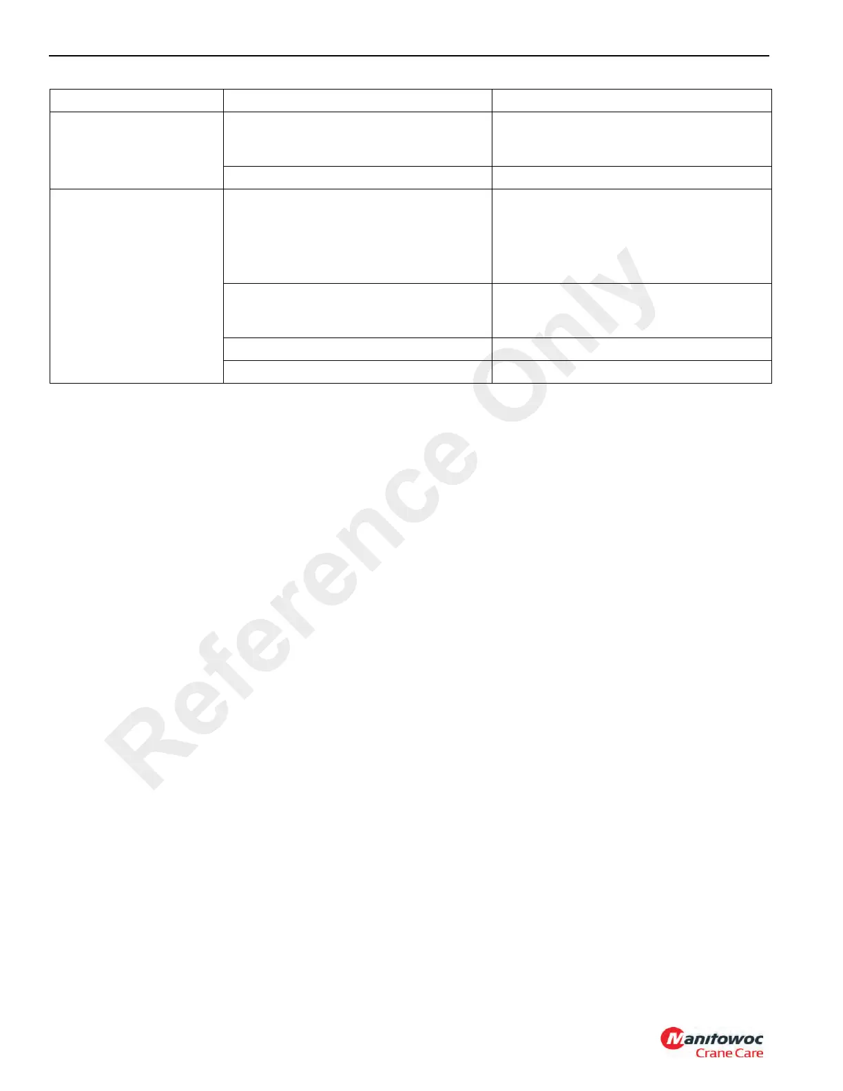
4. Noisy hydraulic pump
caused by cavitation.
a. Hydraulic oil low. a. Refill hydraulic reservoir. Refer to
Maintenance and Lubrication, page
9-1.
b. Suction line plugged or too small. b. Clean line and check for size.
5. Hydraulic pump shaft
seal
leakage.
a. Worn shaft seal.
NOTE: If replacing the shaft seal does not
stop leakage, the pump should be
disassembled and checked for the
following:
a. Replace shaft seal.
b. Broken diaphragm seal or backup
gasket.
b. Replace seal or gasket. Refer to your
Manitowoc Crane Care Parts
Manual.
c. Bearing out of position. c. Replace bearing.
d. Excessive internal wear. d. Replace pump.
Symptom Probable Cause Solution
Reference Only

 Loading...


