UNDERCARRIAGE GRT880 SERVICE MANUAL
8-10
Published 10/19/2017, Control # 618-00
REAR AXLE OSCILLATION LOCKOUT
SYSTEM
Description
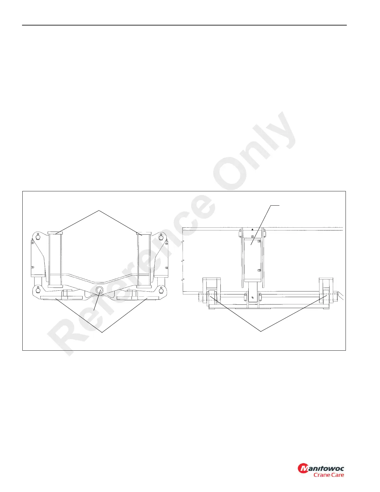
The rear axle oscillation system Figure 8-11 and Figure 8-12
consists of two lockout cylinders, a lockout valve, and an
angle encoder. The lockout cylinders are mounted between
a cradle (fifth wheel) and the carrier frame. The lockout valve
is mounted on the left inner center frame rail and
hydraulically controls the oscillating abilities of the lockout
cylinders. The angle encoder is located in the electrical
swivel assembly.
Theory Of Operation
The rear axle is mounted on a cradle (fifth wheel) allowing
maximum oscillation of 25.4 cm (10 in) total while traveling
over uneven terrain. Oscillation is provided only when the
superstructure is within 3° left or right of directly over the
front. When the superstructure is within 3° left or right of
directly over the front, the RCL sends a CAN bus message to
the Crane Control System to allow axle oscillation. When the
Crane Control System receives this message it switches ON
a digital output thus energizing the axle oscillation solenoids.
When the solenoids are energized, the valve spools are
shifted to allow hydraulic transfer between the two lockout
cylinders. As one side of the axle is forced up by traveling
over uneven terrain, the hydraulic oil flows from the rod end
of cylinder A to the barrel end of cylinder B and from the rod
end of cylinder B to the barrel end of cylinder A. The system
is not pressurized and oil is moved from one cylinder to the
other by the action of the axle moving the cylinder.
When the superstructure is more than 3° left or right of
directly over the front, the Crane Control System switches
OFF the digital output thus de-energizing the axle oscillation
solenoids. This de-energizes the solenoids on the lockout
valve and allows the springs in the valve to shift the valve
spools to the closed position to prevent hydraulic oil flow
between the cylinders. By stopping the flow of oil, a hydraulic
lock is created and the axle is held rigid in that position.
Pivot Point
Pivot Point
Oscillation Lockout
Cylinder
Carrier Frame
Fifth Wheel
B
A
FIGURE 8-11
Reference Only

 Loading...


