3-7
Published 10/19/2017, Control # 618-00
GRT880 SERVICE MANUAL ELECTRICAL SYSTEM
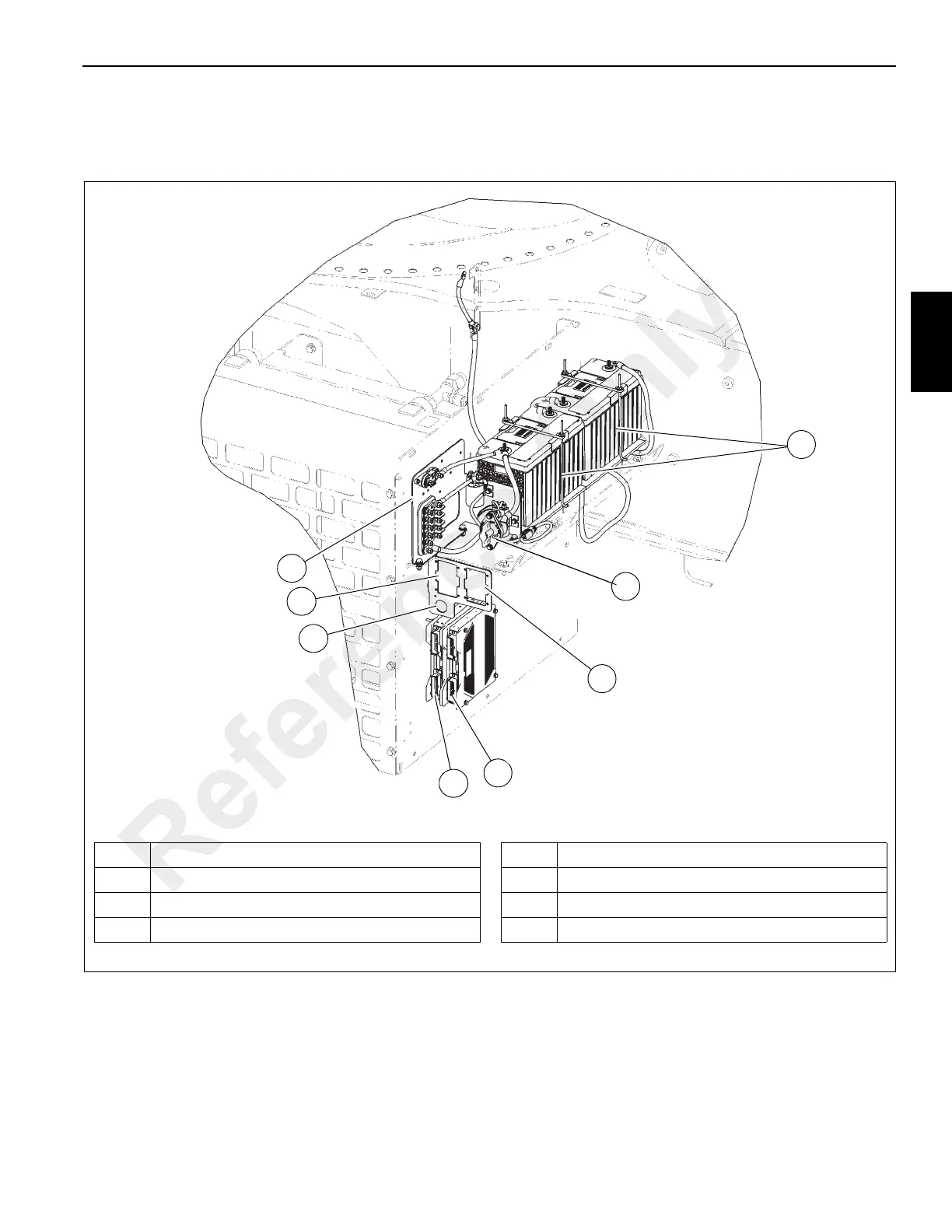
Carrier Electrical Panel
The carrier electrical panel (Figure 3-6) is located on the fuel
tank side of the crane, inside the electrical compartment. It
consists of the two batteries, battery disconnect switch, fuse
and relay boxes, starter and grid heater relays, and
electronic control units.
1 Batteries - 12V
2 Battery Disconnect Switch
3 Fuse and Relay Box 2 (see Figure 3-9)
4 Electronic Control Unit - MWI0L
5 Electronic Control Unit - MWCCM
6 J1939 Diagnostic Connector
7 Fuse and Relay Box 1 (see Figure 3-8)
8 Fuse Panel (see Figure 3-7)
FIGURE 3-6
1
2
4
5
8
3
6
7
Carrier Electrical Panel
Reference Only

 Loading...


