2-33
GRT880 SERVICE MANUAL HYDRAULIC SYSTEM
Published 10/19/2017, Control # 618-00
Checking the Service Brake Accumulators
Pre-charge
1. With the engine off, discharge all of the pressurized oil
stored in the accumulators by depressing the service
brake pedal on the cab floor 4 to 6 times.
2. Remove the gas valve guard and cap on the
accumulator (see Figure 2-12).
3. Before attaching the gas charging assembly (see
Figure 2-12) onto the gas valve, fully turn the gas chuck
“T” handle counter-clockwise until it stops.
4. Close the charging assembly bleed valve. Attach the
swivel nut onto the gas valve and tighten (10-15 in-lb).
5. Fully turn the gas chuck “T” handle clockwise which will
depress the core in the gas valve.
6. Check the pre-charge pressure. The gauge should read
1500 to 1550 psi (103 to 107 bar).
If the pressure is 1500 to 1550 psi (103 to 107 bar),
remove the charging valve assembly by fully turning the
“T” handle counter-clockwise on the gas chuck, then
open the bleed valve and proceed to step 7 (see
Figure 2-12). If the pressure is low, proceed to the
procedure Pre-charging the Accumulators, page 2-34.
7. Secure the gas valve, loosen the swivel nut and remove
the charging assembly. Replace the gas valve cap and
guard.
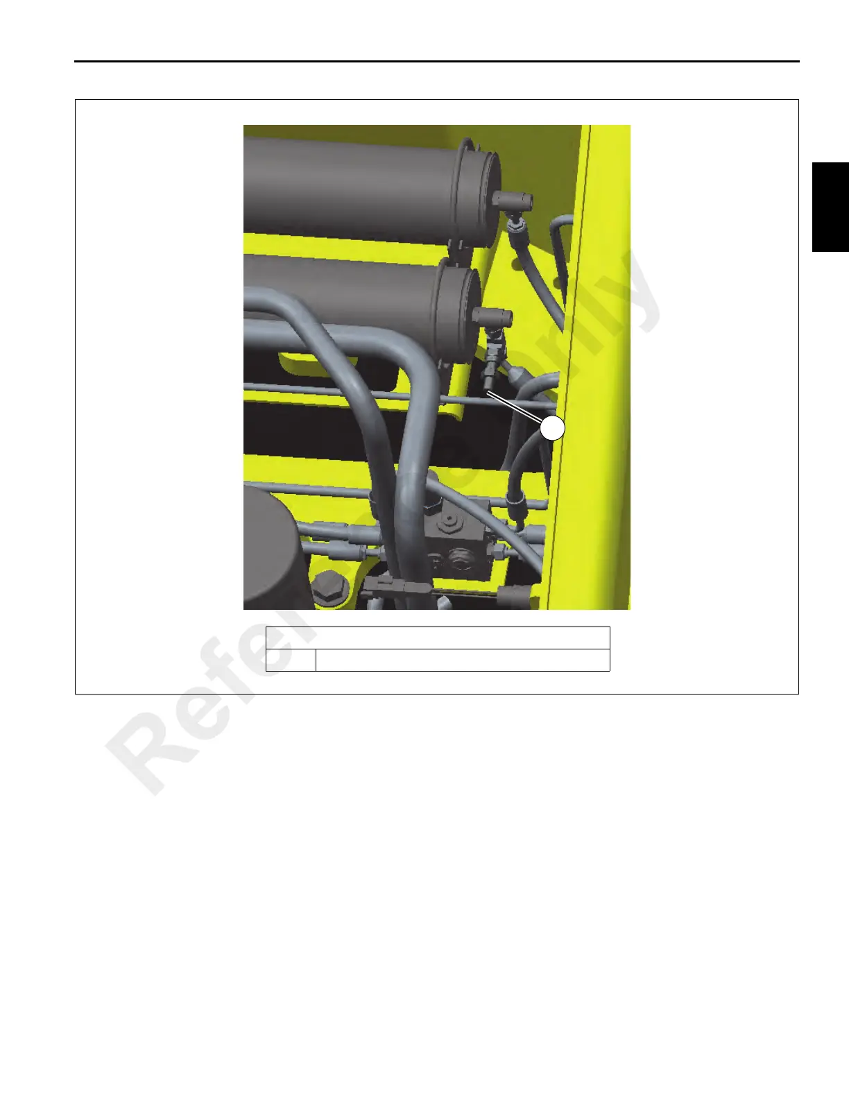
Brake Pressure Port Location
1 Brake pressure port
8804-68
FIGURE 2-11
1
Reference Only

 Loading...


