HYDRAULIC SYSTEM GRT880 SERVICE MANUAL
2-24
Published 10/19/2017, Control # 618-00
Checking/Setting the Piston Pumps Cut-off
and Differential Pressures
1. With engine off, install a pressure check diagnostic quick
disconnect (p/n 9999101806) with gauge onto the test
nipple at pump No. 1 gauge port (see Figure 2-5).
2. If the lift or tele cylinders are not
installed, plug the
hoses. If the cylinders are installed, skip this step.
3. Start engine and idle. Turn the differential pressure
adjustment screw (see Figure 2-5) on pump No. 1
clockwise to increase or counter-clockwise to decrease
so that a gauge reading of 375 to 425 psi (26 to 29 bar)
is achieved.
4. Stop engine and remove the diagnostic coupler.
5. With engine off, install a pressure check diagnostic quick
disconnect with gauge onto the test nipple at pump No. 2
gauge port (see Figure 2-5).
6. Start engine and idle. Turn the differential pressure
adjustment screw (see Figure 2-5) on pump No. 2
clockwise to increase or counter-clockwise to decrease
so that a gauge reading of 425 to 475 psi (26 to 33 bar)
is achieved.
7. Stop engine and remove the diagnostic coupler.
8. Adjust the cut-off maximum pressure settings on the No.
1 and No. 2 pumps by performing the following steps:
a. On both pumps, loosen the jam nut on the cut-off
pressure adjusting screw (see Figure 2-5) and turn
it fully clockwise.
b. On both pumps, turn the adjusting screw counter-
clockwise ½ turn and lock in place with the jam nut.
c. This will ensure that full system pressure of 4000 psi
(276 bar) can be obtained in the procedure
Checking/Setting the Main Directional Control
Valve, Hoists, Lift, and Telescope Pressures, page
2-26.
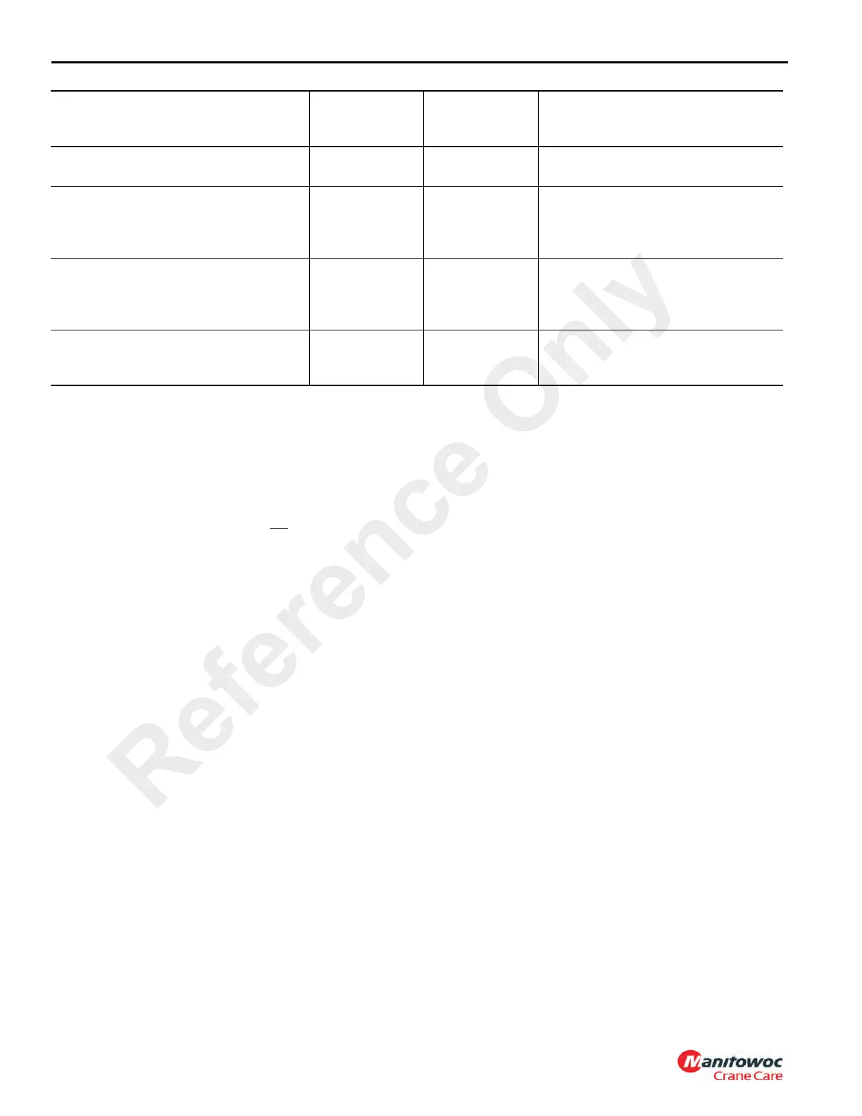
Service brake accumulator pre-charge
1500 to 1550
(103 to 107)
See range Accumulator (see Figure 2-12)
Outriggers, rear steer & hyd/trans oil
cooler fan motor pressures
2750 (190) ±50 (4)
G2 port on carrier combo valve (see
Figure 2-14); adjust pressure reducing
valve on carrier combo valve (see
Figure 2-15)
Axle lockout pressure 100 (7) ±25 (2)
G3 port on carrier combo valve (see
Figure 2-14); adjust pressure reducing
valve on carrier combo valve (see
Figure 2-15)
Luffing jib pressure 4000 (276) ±100 (7)
G port on luffing jib valve, adjust luffing
jib relief valve on luffing jib valve (see
Figure 2-16)
VALVE TO BE SET
GAUGE
PRESSURE
PSI (bar)
TOLERANCE
PSI (bar)
GAUGE PORT & ADJUSTMENT
LOCATION
Reference Only

 Loading...


