HYDRAULIC SYSTEM RT770E
2-26
Published 11/26/2014, Control # 447-05
Procedure E - Charge Air Cooler Valve Relief
Pressure
1. Install pressure check diagnostic quick disconnect
(Parker PD240) with gauge onto Test Port, Figure 2-9.
2. Unplug CAC Solenoid.
3. Start engine and operate at Full RPM. Adjust “CAC Fan
Relief Valve” to 69 bar +4/-0 (1000 psi +50/-0)
NOTE: Note: If brake valve begins charging accumulators,
test port pressures above 124.1 bar (1800 psi) may
be observed. Wait until charge is complete and
then adjust CAC Relief to 69 bar +4/-0 (1000 psi
+50/-0).
4. Remove pressure gauge from the Test Port, and
reconnect CAC Solenoid.
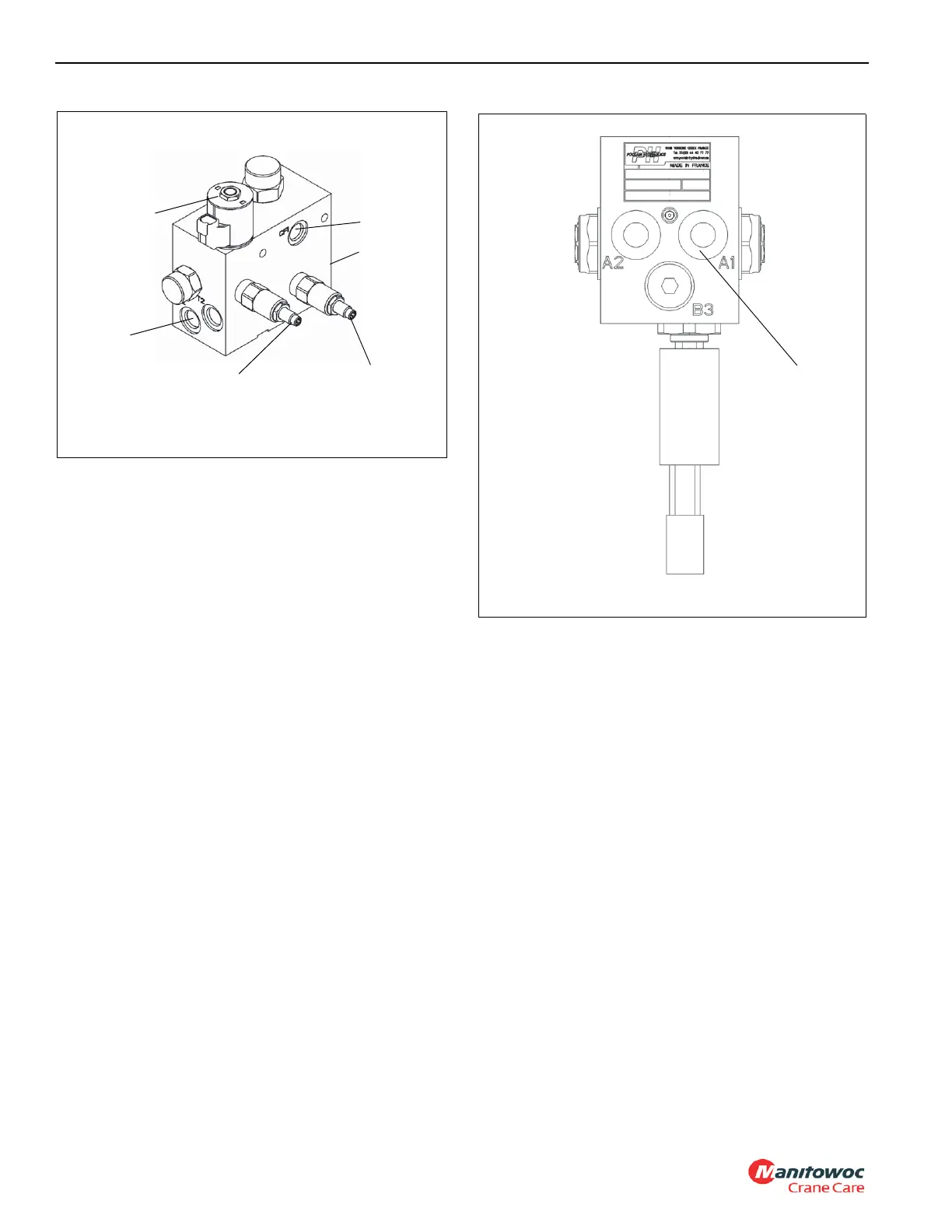
Procedure F - Brake Dual Accumulator
Charge Valve Pressure Limits
1. With the engine off, discharge all of the pressurized oil
stored in the accumulators by depressing the service
brake pedal on the cab floor 8-10 times.
2. Install a pressure gauge at the service brake dual
accumulator charge valve “A1” pressure test port (1,
Figure 2-10).
3. Start and idle the engine. The charging valve will
immediately start to charge the accumulators. Watch the
pressure gauge. The high charge limit pressure should
read 174 bar +5/-10 (2320 psi +72/-145) when the valve
stops charging. The accumulator charge valve is non-
adjustable.
4. With the engine running, bleed off the hydraulic pressure
stored in the accumulators by pushing the service brake
pedal on the cab floor until the gauge reads about
134 bar (1950 psi). Listen to hear when the service
brake dual accumulator charge valve starts to recharge.
Push the service brake pedal once more; the valve
should start to recharge. Watch the pressure gauge. The
low charge limit should be 134 bar ±10 (1950 psi ±145)
when the valve starts to recharge. The accumulator
charge valve is non-adjustable.
5. Turn engine off. Remove the pressure gauge.
Procedure G - Accumulator Pre-Charge
Pressure
1. With the engine off, discharge all of the pressurized oil
stored in the accumulators by depressing the service
brake pedal on the cab floor several times. Remove the
gas valve guard and cap on the accumulator
Figure 2-11.
2. Before attaching the gas charging assembly Figure 2-11
onto the accumulator gas valve, back the gas chuck “T”
handle all the way out (counterclockwise).
3. Close the charging assembly bleed valve. Attach the
swivel nut onto the gas valve and tighten to 1.1 to
1.7 Nm (10 to 15 lb-in).
Tes t P or t
FIGURE 2-9
7798
CF1 Port
Adjustable Inlet
Relief Valve
CF2 Port
Adjustable
CAC Fan
Relief Valve
CAC Solenoid

 Loading...


