2-55
RT770E HYDRAULIC SYSTEM
Published 11/26/2014, Control # 447-05
TELESCOPE STAGE SELECTOR VALVE
MANIFOLD
Description
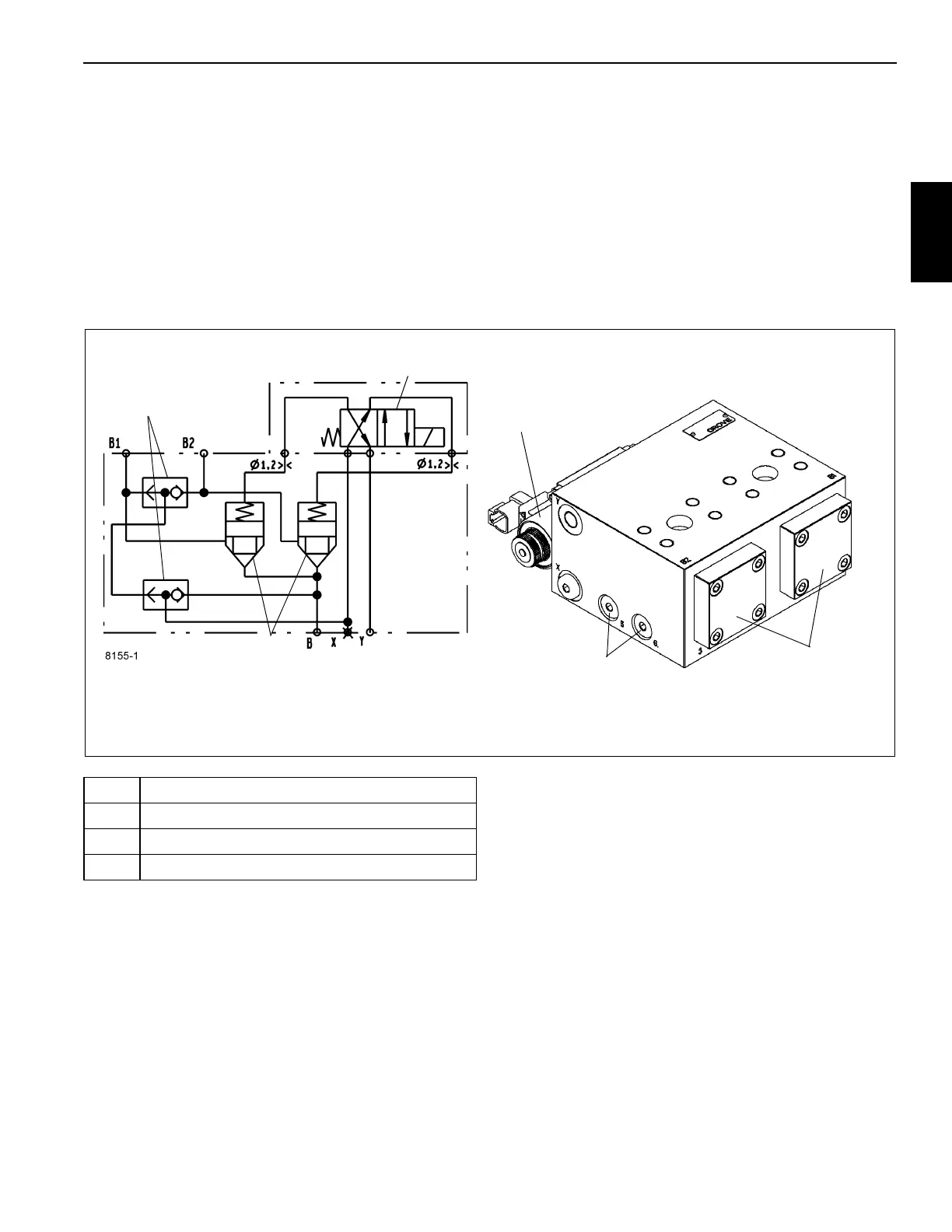
The software sends output signals to the Telescope Stage
Selector Valve Manifold, based on inputs from the operator
controlled Mode Selector Switches in the cab and the
cylinder length sensing components, to control whether the
first or second stage of the telescope cylinder extends and
retracts first or second. The manifold consists of two pilot-
operated poppet valves(1); one spring offset, solenoid
controlled, four-way directional control valve (2); and two
shuttle valves (3). The oil flow from the Telescope Directional
Control Valve is split after entering the Telescope Stage
Selector Valve Manifold and goes to the two poppet valves.
One poppet valve controls oil flow to the first stage and the
other poppet valve controls oil to the second stage. Whether
extending or retracting, pilot oil from one of the working lines
passes through the shuttle valve(s) to the solenoid controlled
directional control valve, which diverts the pilot oil to close
the appropriate poppet valve, which then allows oil to flow to
or from the selected cylinder stage through the other poppet
valve.
Maintenance
Removal
1. Tag and disconnect the electrical connectors to the
valve.
2. Tag and disconnect the hydraulic hoses from the valve.
Cap or plug the lines and ports.
3. Remove the capscrews, lockwashers, flatwashers
securing the valve. Remove the valve.
Installation
1. Secure the valve with the nuts, flatwashers, lockwashers
and capscrews. Torque capscrews; refer to Fasteners
and Torque Values, page 1-16 for proper torque value.
2. Connect the hydraulic hoses to the ports on the valve as
tagged during removal.
3. Connect the electrical connectors to the valve as tagged
during removal.
Valve Hydraulic Schematic
FIGURE 2-31
2
1
3
2
3
1
Item Description
1 Pilot Operated Poppet Valves
2 Four-way Directional Control Valve
3 Shuttle Valves

 Loading...


