BOOM RT770E SERVICE MANUAL
4-32
Published 11/26/2014, Control # 447-05
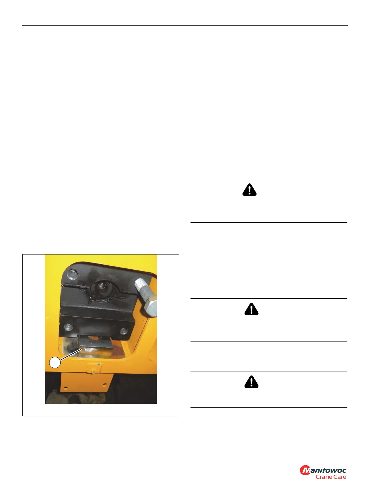
121.Install the left, right, and bottom keeper plates (2x-14,
13) to the front of the base section (1) using the bolts
(19), flat washers (16), lock washers (17), and nuts (18)
(see Figure 4-57).
122.Install the plate (12) to the inside of the base section (1)
using the two bolts (20) and flat washers (16) (left and
right sides).
123.Fully insert tele 1 (2) into the base section (1).
124.Locate and weld the two wedges (29) to the base
section (1) by doing the following (see Figure 4-58):
a. Position the wedges (29) between the telescope
cylinder (6) and the plates on the trunnion.
b. Center the telescope cylinder (6) between the top
and bottom plates.
c. Bolt the telescope cylinder in place using the two
plates (30) and four bolts (31).
d. Tack weld the two wedges (29) to the plates of the
trunnion.
e. Remove the four bolts (31) and two plates (30).
f. Remove the telescope cylinder (6) from the trunnion
area, then weld the two wedges (29) in place.
g. Reattach the telescope cylinder (6) to the base
section (1) using the two plates (30) and four bolts
(31).
125.Install the transducer (151) into the end of the telescope
cylinder (6).
126.Mount the tele stage selection manifold (37) to the
bottom rear of the base section (1) using the four bolts
(20) and flat washers (16).
127.Install all hydraulic tube assemblies to the tele stage
selection manifold (37) and telescope cylinder (6) as tag
during disassembly; replace all O-rings.
128.Once the boom assembly is positioned right-side up,
adjust the top front wear pads (11, 92, 103) of each
boom tele section using the upper and side adjustment
bolts (27). Adjust the wear so that they are just touching
or are no more than 2 mm (0.08 in) away from
contacting the next inner tele section. Tighten the jam
nuts.
Installation
NOTE: The following procedure applies to a boom totally
removed from the crane.
1. Attach an adequate lifting device to the boom and
suspend the boom over the machine.
2. Lower the boom into position and align the boom pivot
shaft mounting holes for installation of the pivot shaft to
the superstructure assembly.
3. Lubricate and install the boom pivot shaft. Secure in
place with the locknut and capscrew. Install the grease
fitting in each end of the shaft.
4. Block the boom in place.
5. Attach a suitable lifting device to the lift cylinder.
6. Using the lifting device attached to the boom, lower the
boom onto the lift cylinder rod end and extend the lift
cylinder as necessary to align rod with attach fitting on
boom.
WARNING
Ensure the lifting device is capable of supporting the
boom assembly. Death or serious injury may result if the
lifting device cannot support the load.
DANGER
Block the boom before doing any work under the boom.
Failure to properly support the boom may result in death
or serious injury.
DANGER
Failure to properly support the boom lift cylinder may
result in death or serious injury.
 Loading...


