4-31
Published 11/26/2014, Control # 447-05
RT770E SERVICE MANUAL BOOM
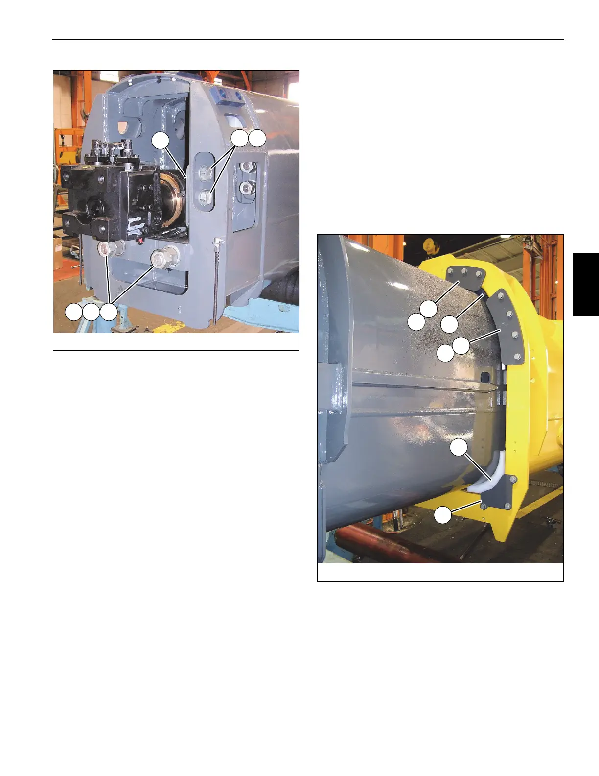
107.Install the two bolts (76) that pass through the anchor
plate (73) into the holes in the rear of tele 1 (2), then
secure in place with the four nuts (75) and two (flat
washers (74) (see Figure 4-56).
108.Mount the wear pad assembly (82) to each side of the
bottom rear of tele 1 (2) using the two capscrews (83).
109.Mount the wear pad assembly (71) to each side of the
bottom rear of tele 1 (2) using the two capscrews (83)
and lock washers (72).
110.Attach the grease hose (81) and related parts (79, 80,
77, 78) to each rear top wear pad (59), then install the
wear pad/grease hose assembly into the attaching
bracket on each side of tele 1 (2).
NOTE: Do not allow the wear pad (59) to hang from the
grease hose, as the threads of the wear pad can be
damaged. If wear pad threads are damaged,
replace the wear pad; do not try to repair with
thread tape.
111. Position the base section (1) up side down and behind
tele 1 (2); set the base section (1) on adequate supports.
112.Using a grease gun or brush, apply grease to the inside
of the base section (1) in the areas where the tele 1 rear
wear pads will touch upon assembly.
113.Align the base section and tele 1 with each other, then
partially insert the tele 1 (2) into the base section (1).
114.Use the shims (70) to adjust the tele 1 rear wear pad
assemblies (71, 82) such that the wear pads are within
2 mm (0.08 in) of the sides and the bottom of the base
section. An equal number of shims should be used on
each side.
115.Insert tele 1 (2) three-quarters of the way into the base
section (1).
116.Using an adequate lift and sling, slightly raise the front of
tele 1 (2) for the purpose of installing wear pads into the
front of the base section (1).
117.Install the upper wear pad (11) into the front of the base
section (1) using the two bolts (27) and nuts (28) (left
and right sides); ensure the thin portion of the upper
wear pad (11) is oriented to the side of the base section
(1) (see Figure 4-57).
118.Install the keeper plate (15) to the front of the base
section (1) using the three bolts (19), six flat washers
(16), three lock washers (17), and three nuts (18) (left
and right sides) (see Figure 4-57).
119.Lower tele 1 (2) down onto the newly installed wear pads
(11).
120.Install the shims (2x-7) and the front lower wear pads (8,
9) into the bottom of the base section (1) (see
Figure 4-57).
FIGURE 4-56
8008-31
60
61 62
74 75 76
FIGURE 4-57
8008-32
9
8
14
7
13
11
15
 Loading...


