4-13
Published 11/26/2014, Control # 447-05
RT770E SERVICE MANUAL BOOM
Disassembly
NOTE: The boom assembly must be rotated 180° (upside
down) before performing any assembly or
disassembly procedures.
Use the following procedures and refer to Figure 4-2 when
disassembling the boom.
1. Remove the boom in accordance with the REMOVAL
procedures outlined in this section.
2. Position the boom assembly upside down on adequate
supports.
3. Tag and remove all hydraulic tube assemblies from the
tele stage selection manifold (37) and telescope cylinder
(6); cap and plug all openings.
4. Remove the four bolts (20) and flat washers (16)
securing the tele stage selection manifold (37) to the
bottom rear of the base section (1).
5. Remove the transducer (151) from the end of the
telescope cylinder (6).
6. Remove the two plates (30) and four bolts (31) securing
the telescope cylinder (6) to the base section (1).
7. Working at the front of the base and tele sections 1, 2, 3,
4, loosen the two jam nuts (28) and bolts (27) on all
upper wear pads (11, 92, 103) (left and right sides).
8. Extend tele 1 (2) one-quarter of the ways out of the base
section (1).
9. Using an adequate lift and sling, slightly raise the front of
tele 1 (2) for the purpose of removing the wear pads
from the front of the base section (1).
10. Remove the three bolts (19), six flat washers (16), three
lock washers (17), and three nuts (18) securing the
keeper plate (15) to the front of the base section (1) (left
and right sides) (see Figure 4-3).
11. Remove the two bolts (27) and nuts (28) securing the
upper wear pad (11) to the front of the base section (1)
(left and right sides) (see Figure 4-3).
12. Remove the two bolts (20) and flat washers (16)
securing the plate (12) to the inside of the base section
(1) (left and right sides).
13. Slightly lower tele 1 (2).
14. Remove the bolts (19), flat washers (16), lock washers
(17), and nuts (18) securing the bottom keeper plates
(2x-14, 2x-13) to the front of the base section (1) (see
Figure 4-3).
15. Remove the shims (2x-7) and the front lower wear pads
(8, 9) from the bottom of the base section (1) (see
Figure 4-3).
16. Remove tele 1 (2) from the base section (1); set tele 1
(2) on adequate supports.
17. Remove the wear pad (59)/grease hose assembly (81,
79, 80, 77, 78) from the attaching bracket on each side
of the rear of tele 1 (2).
18. Remove the two capscrews (83) securing the wear pad
assembly (82) to each side of the bottom rear of tele 1
(2).
19. Remove the two capscrews (83) and lock washers (72)
securing the wear pad assembly (71) to each side of the
bottom rear of tele 1 (2).
CAUTION
A rollover fixture with webbing is recommended to rotate
the boom sections. Chains are not recommended. If a
rollover fixture is not available, rotate the sections using
adequate support with webbing.
A secure fixture that will prevent damage to the boom is
recommended to stabilize and hold the boom from moving
during removal of any section or sections.
When removing the extend and retract cables, hold the
cable end and turn the nut. Do not turn the cable. Turning
the cable will result in damage or failure of the cable.
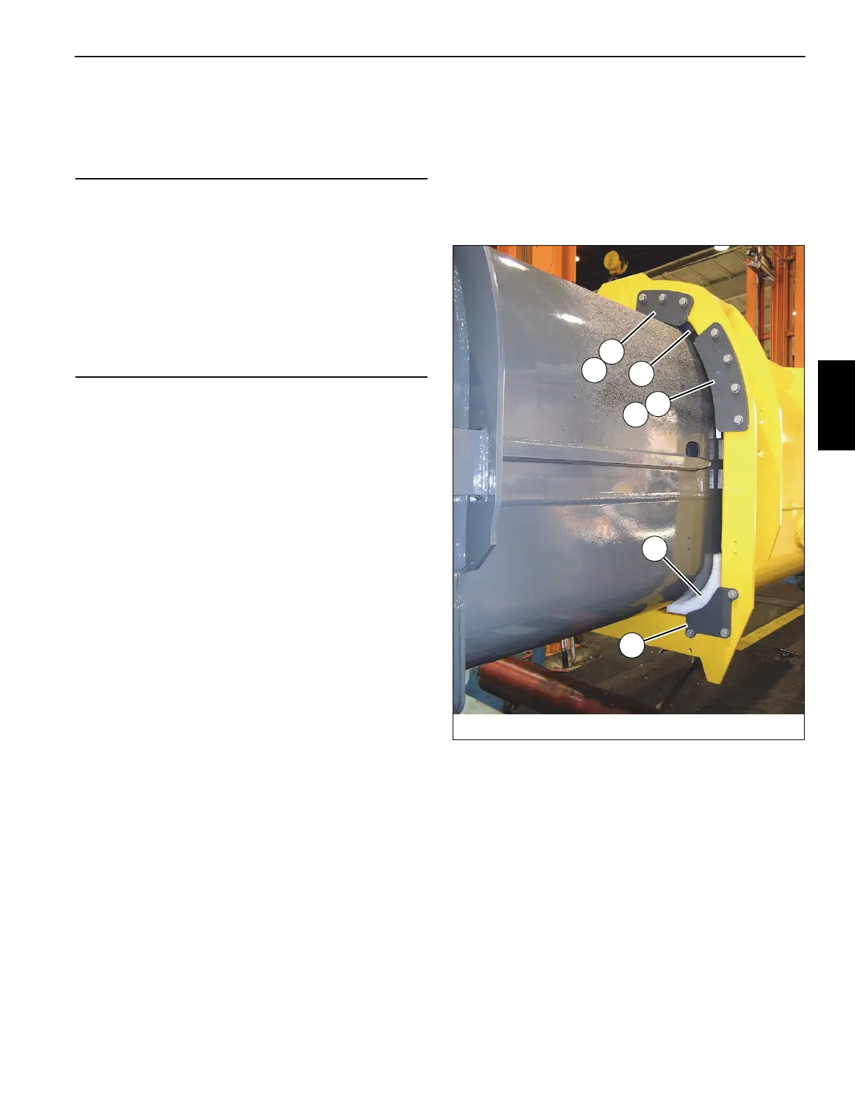
FIGURE 4-3
8008-32
9
8
14
7
13
11
15
 Loading...


