BOOM RT770E SERVICE MANUAL
4-14
Published 11/26/2014, Control # 447-05
20. Remove the four nuts (75) and two flat washers (74)
securing the two bolts (76), which pass through the
anchor plate (73), to the rear of tele 1 (2) (see
Figure 4-4).
21. Remove the five bolts (62) and flat washers (61)
securing the trunnion plate (60) to the inside of tele 1 (2)
(left and right sides) (see Figure 4-4).
22. Slightly extend tele 2 (3).
23. Using an adequate lift and sling, slightly raise the front of
tele 2 (3) for the purpose of removing the wear pads
from the front of tele 1 (2).
24. Remove the three bolts (19), six flat washers (16), three
lock washers (17), and three nuts (18) securing the
keeper plate (15) to the front of tele 1 (2) (left and right
sides).
25. Remove the two bolts (27) and nuts (28) securing the
upper wear pad (11) to the front of tele 1 (2) (left and
right sides).
26. Remove the two bolts (69), four flat washers (67), and
two nuts (18) securing the anchor plate (64) to the top of
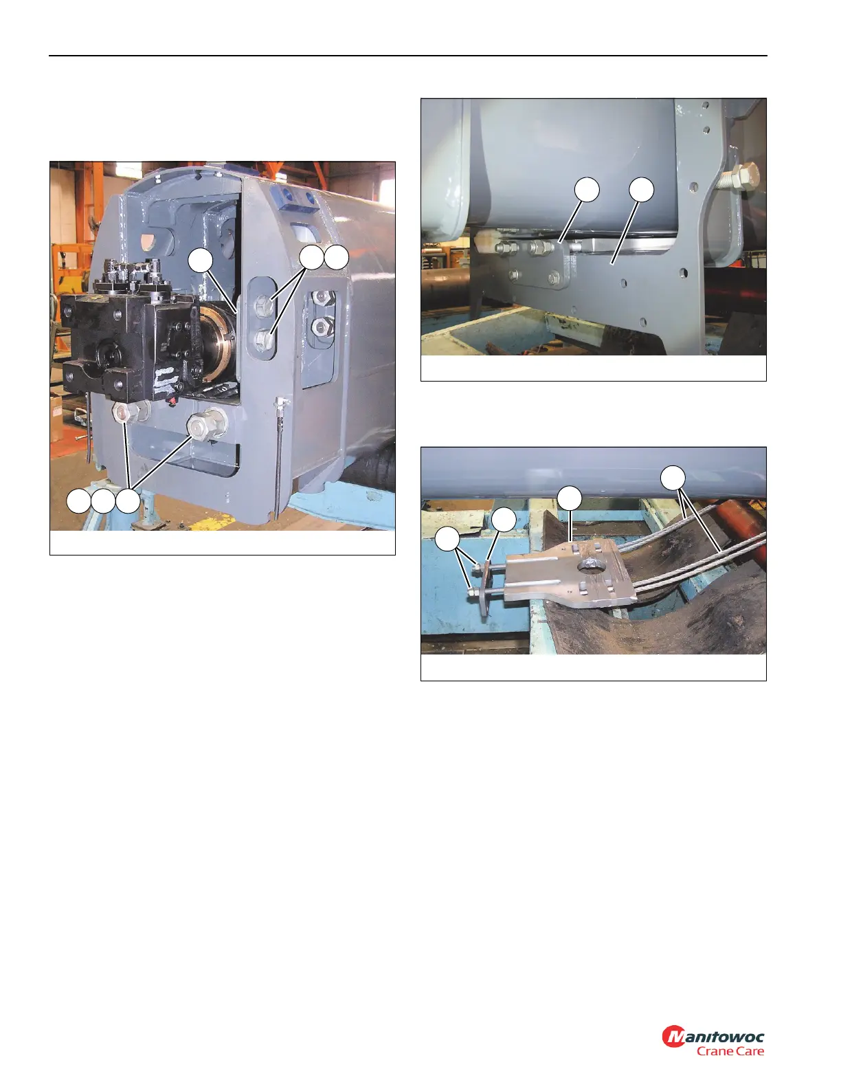
tele 1 (2) (see Figure 4-5).
27. Remove the nuts (66) securing the anchor plate (64) to
the studs of the retract anchor weldment (63) (see
Figure 4-6).
28. Remove the four tele 3 retract cables (65) from the slots
of the retract anchor weldment (63) (see Figure 4-54).
29. Slightly lower the front of tele 2 (3).
30. Remove the two bolts (58), four washers (16), two lock
washers (17), and two nuts (18) securing the stop block
(56) and shim (57) to the front of tele 1 (2) (left and right
sides).
31. Remove the bolts (19), flat washers (16), lock washers
(17), and nuts (18) securing the left, right, and bottom
keeper plates (2x-14, 13) to the front of tele 1 (2).
32. Remove the front lower wear pads (54, 55) and shims
(53) from the bottom of tele 1 (2).
33. Remove tele 2 (3) from tele 1 (2); set tele 2 (3) on
adequate supports.
FIGURE 4-4
8008-31
60
61 62
74 75 76
FIGURE 4-6
8008-29
64
63
65
66
 Loading...


