4-15
Published 11/26/2014, Control # 447-05
RT770E SERVICE MANUAL BOOM
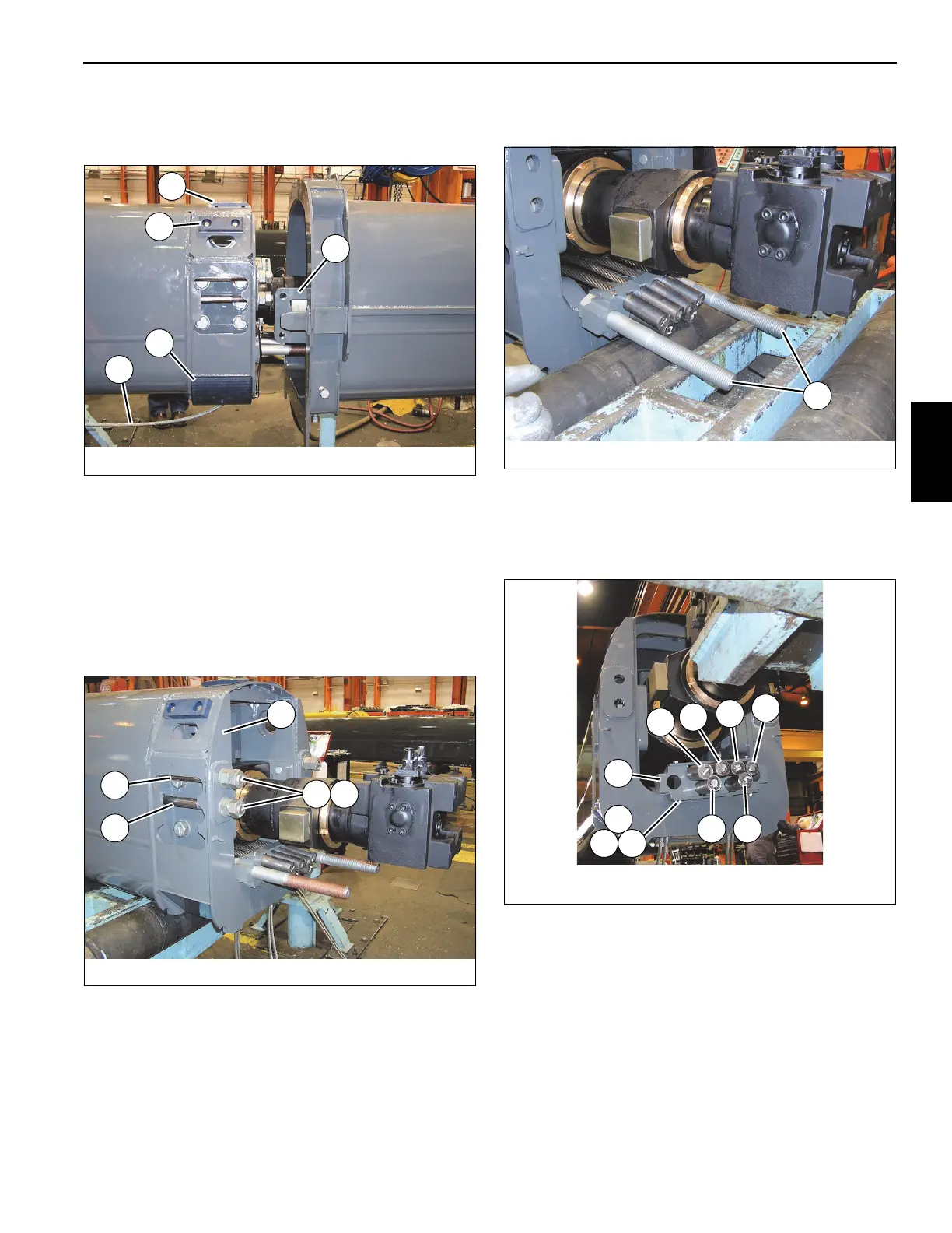
34. Remove the wear pad (94)/grease hose assembly (81,
79, 80, 77, 78) from the attaching bracket on each side
of the rear of tele 2 (3) (see Figure 4-7).
35. Remove the two capscrews (83) and lock washers (72)
securing the wear pad assembly (71) to each side of the
bottom rear of tele 2 (3) (see Figure 4-7).
36. Remove the two capscrews (83) securing the wear pad
assembly (82) to each side of the bottom rear of tele 2
(3) (see Figure 4-7).
37. Remove the two nuts (95) and one flat washer (61)
securing each of the four tele 4 extends cables (109,
110) to the top rear of tele 2 (3) (see Figure 4-8).
38. Remove the two tele 4 extend cables (109, 110) from the
holes in the rear of tele 2 (3) (left and right sides) (see
Figure 4-8).
39. Remove the two bolts (76) from the anchor plate (73)
(see Figure 4-9).
40. Remove the two bolts (85) and lock washers (25)
securing the plate cover (84) to the anchor plate (73),
then remove the four tele 3 extend cables (150), labeled
1, 3, 4, and 6, from the anchor plate (73) (see
Figure 4-10).
41. Remove the two bolts (85) and lock washers (25)
securing the plate cover (84) to the anchor plate (73),
then remove the two tele 3 extend cables (150), labeled
2 and 5, from the anchor plate (73) (see Figure 4-10).
42. Remove the five bolts (62) and flat washers (61)
securing the trunnion plate (60) to the inside of tele 2 (3)
(left and right sides) (see Figure 4-11).
FIGURE 4-7
8008-28
82
71
60
94
65
FIGURE 4-8
8008-27
95
109
110
3
61
FIGURE 4-10
8008-25
#2
#1
#5
#3
#4
#6
25
84
73
85
 Loading...


