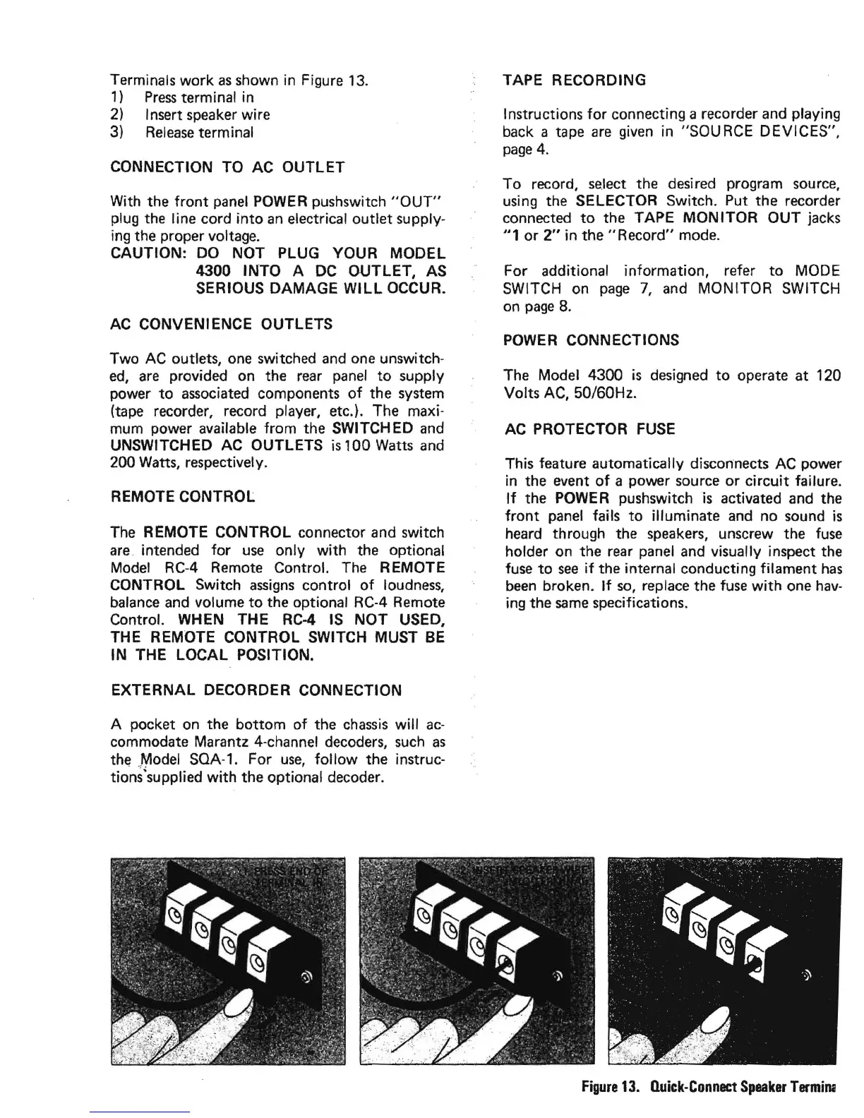
Terminals work
as
shown
in
Figure
13.
1)
Press
terminal in
2)
Insert speaker wire
3)
Release
terminal
CONNECTION TO AC OUTLET
With the
front
panel
POWER
pushswitch
"OUT"
plug the line cord
into
an
electrical outlet supply-
ing the proper voltage.
CAUTION: DO NOT PLUG YOUR MODEL
4300 INTO A
DC
OUTLET, AS
SERIOUS DAMAGE
WILL
OCCUR.
AC
CONVENIENCE OUTLETS
Two
AC
outlets,
one
switched
and
one
unswitch-
ed,
are
provided on the
rear
panel
to
supply
power
to
associated
components
of
the system
(tape recorder, record player, etc.). The maxi-
mum power available from the SWITCHED
and
UNSWITCHED AC OUTLETS
is
100 Watts
and
200 Watts, respectively.
REMOTE CONTROL
The
REMOTE CONTROL connector and switch
are.
intended for
use
only with the optional
Model
RCA Remote Control.
The
REMOTE
CONTROL Switch
assigns
control
of
loudness,
balance
and
volume
to
the optional
RC-4
Remote
Control. WHEN THE
RC-4
IS
NOT USED,
THE REMOTE CONTROL SWITCH MUST
BE
IN THE LOCAL POSITION.
EXTERNAL DECORDER CONNECTION
A pocket
on
the bottom
of
the
chassis
will
ac-
commodate Marantz 4-channel decoders,
such
as
the
.~odel
SOA-1. For
use,
follow
the instruc-
tions'supplied
with
the optional decoder.
TAPE RECORDING
Instructions
for
connecting a recorder
and
playing
back a tape
are
given
in "SOURCE DEVICES",
page
4.
To record,
se.lect
the desired program
source,
using the SELECTOR Switch. Put the recorder
connected
to
the TAPE MONITOR OUT jacks
"1
or
2"
in
the"
Record" mode.
For additional information, refer
to
MODE
SWITCH on
page
7,
and
MONITOR SWITCH
on
page
8.
POWER
CONNECTIONS
The Model 4300
is
designed
to
operate at 120
Volts
AC,
50/60Hz.
AC PROTECTOR
FUSE
This feature automatically disconnects AC power
in
the event
of
a power source
or
circuit failure.
If
the
POWER
pushswitchis activated
and
the
front
panel
fails
to
illuminate
and
no sound
is
heard through the
speakers,
unscrew the
fuse
holder on the
rear
panel
and
visually inspect the
fuse
to
see
if
the internal conducting filament
has
been
broken.
If
so,
replace the
fuse
with
one
hav-
ing the
same
specifications.
Figure
13.
Quick-Connect
Speaker
Tennin;