Following the AM IF amplifier, the AM detector
recovers
the audio modulation
and
provides this
signal
to
the SELECTOR Switch.
The
AM tuner
and
IF amplifier incorporates
an
automatic
gain
control circuit which maintains
a constant
level
of
all stations in the AM band.
An
advanced
AM tuner integrated circuit
has
been
utilized
for
the AM tuner portion
of
the
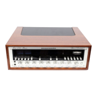
Model 4300.
PHONO AMPLIFIERS
These
amplifiers permit phono
signals
of
up
to
100 millivolts
to
be
handled
without
overloading.
The
RIAA
equalization network provides precise
equalization
and
sets
the phono preamplifier
voltage
gain
to
40
dB
(at 1,oooHz).
SELECTOR SWITCH
The SELECTOR Switch
selects
the program
source
for listening
or
recording. The Model
4300
has
four
sets
on input jacks: PHONO, CD·
4/AUX,
TAPE MONITOR 1
and
TAPE MONI-
TOR
2.
Any discrete 4-channel program source
can
be
connected
to
the CD-4/AUX jacks. The
input sensitivity
for
each
set
of
input jacks
is
1.8
millivolts at PHONO,
and
180 millivolts at
CD-
4/AUX,
TAPE MONITOR 1
and
TAPE MONI-
TOR
2.
The SELECTOR Switch outputs
are
fed
through the DOLBY Switch
and
TAPE
MONITOR OUT jacks to the MODE Switch.
MONITOR SWITCH
When
the MONITOR Switch
is
in the SOURCE
position, the SELECTOR Switch outputs
are
fed
through
~~e
DOLBY Switch to the MODE Switch.
When
the MONITOR Switch
is
in TAPE 1
or
TAPE 2 positions, the input
signals
from the
TAPE MONITOR
(1
or
2) jacks
are
fed
to
the
DOLBY Switch.
TONE CONTROL
After
volume
level
control,
each
channel program
source
is
fed
into
the tone control network. The
network
uses
two-stage, direct-coupled
NPN
and
PNP
configuration at the input
stage
for
the high-
impedance termination
of
the volume control
output,
and
low driving impedance
to
the
R-C
feed
back type tone control network. In the
tone control network,
each
signal
adjusted
for
bass
and
treble
is
amplified in two-stage, direct-
coupled
NPN
and
PNP
configuration
and
is
delivered through a HIGH FILTER Switch
to
the
main amplifier section. The driving impedance
to
the balance high
filter
section
is
satisfactorily
reduced
by
NFB.
POWER
AMPLIFIER
Your power amplifiers
are
incorporated
for
driv-
ing left-front, left-rear, right-front
and
right-rear
speakers.
Each
of
these
amplifiers includes
pre-
amplifier, driver, electronic protective
and
output
circuits.
These
amplifiers consists
of
four
totally
direct-coupled
and
differential amplifiers
to
pro-
vide superior dynamic characteristics, frequency
response
and
satisfactory D.C. stability. The
output
stages
employ eight high current, high
voltage, silicon
output
transistors, having superior
linearity
and
sufficient collector dissipation
margin, arranged in a quasi-complimentary
Darlington format.
DRIVER STAGE
This
stage
incorporates a pair
of
push-pull,
complimentary-symmetry transistors
(PI\lP,
NPN).
The electronic protective circuit comprised
of
three transistors
and
four
diodes
for
each
channel,
senses
the
peak
output
current
and
limits the
current
to
the driver transistors at a
safe,
pre-
determined value. This limiting current protects
the driver
and
output
transistors under over-drive
and
short circuit conditions
and
effectively
pre-
vents the driver
and
output
transistors from
exceeding
safe
operating conditions.
GENERAL
REQUIREMENTS
Power Requirements
.....
120V AC 50
to
60Hz
Power
Consumption
- at rated power output, all channels· 650W
- idling (no signal) "
60W
Dimensions -
Panel
Width··
..
·19·19/64 inches
-
Panel
Height . . . . 5-3/4
inches
- Depth 15-3/16 inches
Weight -
Unit
alone· 51.6
Ibs
-
Packed
for
shipment 62.7
Ibs