FRONT
PANEL
FEATURES
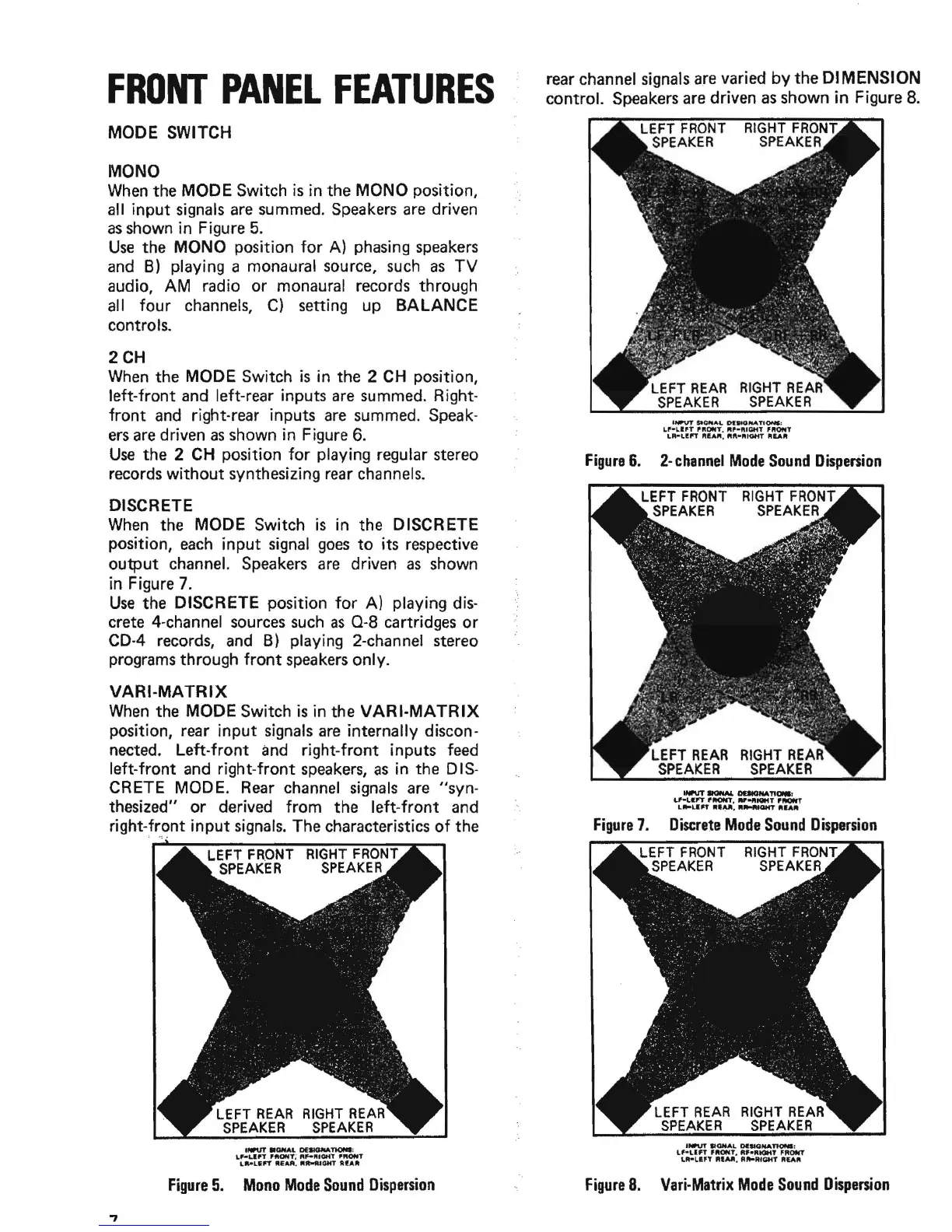
MODE SWITCH
MONO
When
the MODE Switch
is
in the MONO position,
all input
signals
are
summed.
Speakers
are
driven
as
shown in Figure
5.
Use
the MONO position
for
A) phasing
speakers
and
B)
playing a monaural source,
such
as
TV
audio, AM radio or monaural records through
all four channels,
C) setting up
BALANCE
controls.
2CH
When
the MODE Switch
is
in the 2
CH
position,
left-front
and
left-rear inputs
are
summed. Right-
front
and
right-rear inputs
are
summed.
Speak-
ers
are
driven
as
shown in Figure
6.
Use
the 2
CH
position
for
playing regular stereo
records
without
synthesizing
rear
channels.
DISCRETE
When
the MODE Switch
is
in the DISCRETE
position,
each
input
signal
goes
to
its respective
output channel.
Speakers
are
driven
as
shown
in Figure
7.
Use
the DISCRETE position
for
A) playing
dis-
crete 4-channel
sources
such
as
0-8
cartridges or
CD-4
records,
and
B)
playing 2-channel stereo
programs through
front
speakers
only.
VARI-MATRIX
When
the MODE Switch
is
in the
VARI·MATRIX
position, rear input signals
are
internally discon-
nected. Left-front
and
right-front inputs feed
left-front and right-front
speakers,
as
in the D
IS-
CR
ETE
MOD
E.
Rear
channel
signals
are
"syn-
thesized" or derived from the left-front and
right-front
input
signals.
The characteristics
of
the
;
",:.
RIGHT
FRONT
SPEAKER
llWUT
.OHAL
DEaMlNATlONI:
L~UPT
'ftONt~
RF-IlIIOftT
'fWflIT
LII'-L&"
"EAA,
Rtt-fUOHT
AfAlIt
Figure
5.
Mono
Mode
Sound
Dispersion
rear channel
signals
are
varied
by
the DIMENSION
control. Speakers
are
driven
as
shown
in
Figure
8.
LEFT
REAR
RIGHT
REAR
SPEAKER
SPEAKER
'NI'VT
SleMA
..
0IW10fli&A.T10N1:
LP-L,lfT
'''ONT.
"'-ft'a.iT
'''ONT
LR-LI!"
..
!.Aft,
..
"
....
tGHT
IlIEAlit
Figure
6.
2-
channel
Mode
Sound
Dispersion
Figure
7.
Discrete
Mode
Sound
Dispersion
LEFT
FRONT
RIGHT
FRONT
SPEAKER
SPEAKER
INPUT SIGNAL
oeIlONA~;
Lf-un
'''ONT,
R,."tQHT
fROflIT
L
...
un
"1M,
"
......
'aHT
"£A"
Figure
8.
Vari·Matrix
Mode
Sound
Dispersion