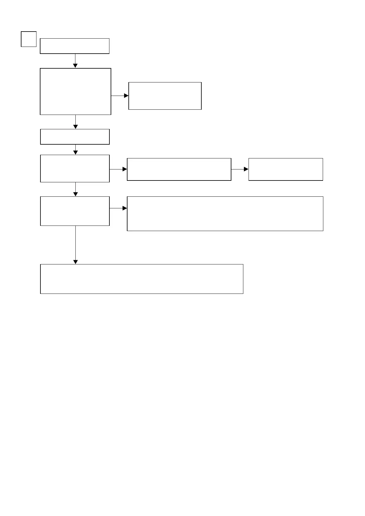
Input
CVBS
B
Check the settings of each IC.
Are the following voltages
set?
HDMI PCB
N1039 - 12 pin : Hi (3.3 V)
N1039 - 13 pin : Hi (3.3 V)
N1039 - 14 pin : Lo (0 V)
Is the power voltage being
output correctly?
V+5V : C5029 : + side
V-5V : C5031 : - side
Is a signal being output from
the video amplier?
CVBS : J5028
: JACK5000 : C-OUT
• Check the connection between the FRONT CONNECTOR PCB and the VIDEO PCB.
• Check the soldering of CP3401 and CP5000 on the FRONT CONNECTOR PCB.
• Check the soldering of CN5000 on the VIDEO PCB.
• Check the soldering of JACK5000 on the VIDEO PCB.
• Check the IC5001 power voltage and check the soldering of the surrounding circuits.
• The pattern between IC5001 and JACK5000 is faulty.
Extend the HDMI PCB using
the jig.
HDMI PCB faulty.
The regulator part of REG PCB is
faulty.
Check the connection between the FRONT
CONNECTOR PCB and the VIDEO PCB.
NO
NO NO
NO
YES
YES
YES
b
These instructions refer to the VIDEO PCB unless otherwise specied.
w
q
e
r
76