8
4
Features and Protection
INTRODUCTION
This section describes how the DVR
®
functions and
explains its operating features. DVR
®
functions are
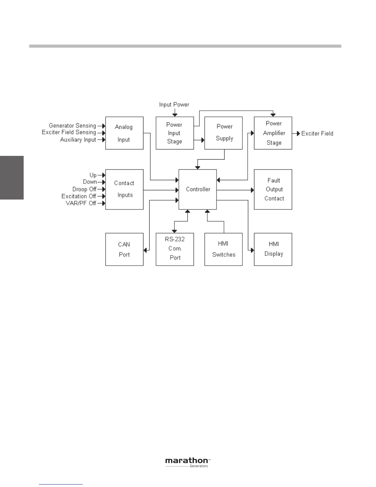
illustrated in the block diagram of Figure 4-1.
DVR
®
FUNCTION BLOCKS
The following paragraphs describe each of the func-
tion blocks, inputs and outputs. Refer to Figure 4-1.
Generator Voltage
Generator voltage is measured at terminals E1
(A-phase), E2 (B-phase), and E3 (C-phase), for ABC
rotation, or E1 (C-phase), E2 (B-phase), and E3
(A-phase) for CBA Rotation. Nominal voltages of up
to 600Vac may be sensed at these terminals. Voltage
applied to these inputs is scaled, conditioned and
applied to the controller.
Line Currents
Generator line currents (IA, IB, IC) are measured
viaCT’satconnectorJ2orterminalsCT1andCT2.
Current up to 5 Arms may be monitored at these
terminals. These currents are scaled, conditioned
and applied to the controller. Refer to Section 3 –
Specifications, for connector pin assignments.
Field Voltage
Voltage across the regulator field is monitored at
terminals, F+ and F-.
Field Current
Current through the exciter field winding is measured
at terminal F+. Field current is scaled, conditioned
and applied to the input of the controller.
Contact Input Circuits
Five contact input circuits powered from an in-
ternal 3.3 Vdc supply provide input control from
user-supplied contacts: UP, DOWN, DROOP_OFF,
EXCITATION_OFFandVAR/PF_OFF(EC+only).
UP
Closing the UP contact across terminals J1-2 and
J1-4causestheactiveoperatingsetpointtoincrease.
Figure 4-1. Simplified Block Design
GPN046 04-13.indd 8 4/5/13 10:24 AM
 Loading...

