50
7
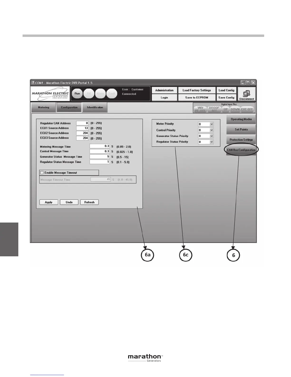
CAN BUS CONFIGURATION (6)
This panel contains editable fields for parameters
associated with the CAN Bus communication of
the DVR
®
. Refer to the DVR2000E+/EC+ CAN Bus
Interface User Guide for a detailed description of
these features.
DVRPortal
™
Graphical User Interface (GUI)
CAN Addresses and Message Times (6a)
This panel allows editing of CAN addresses and
message times.
• Regulator CAN Address is the CAN address
of the DVR
®
.
• ECU1 Source Address is the CAN address
of the highest priority Electronic Control Unit
that the DVR
®
will respond to.
• ECU2 Source Address is the CAN address
of the second-highest priority Electronic
Control Unit that the DVR
®
will respond to.
• ECU3 Source Address is the CAN address
of the lowest priority Electronic Control Unit
that the DVR
®
will respond to.
Note: The ECU addresses can all be assigned to the
same control unit. They should only be different if the
DVR
®
needs to communicate with more than one ECU.
GPN046 04-13.indd 50 4/5/13 10:24 AM