40
7
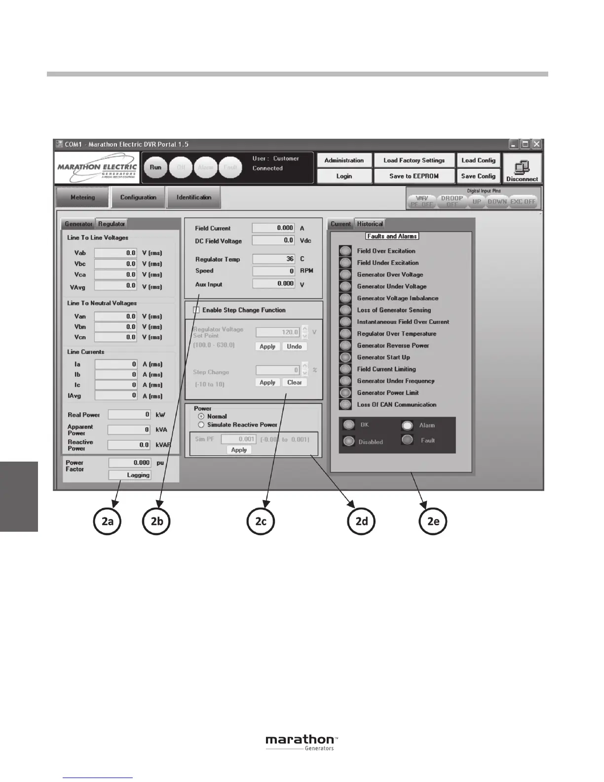
AC Metering (2a)
This panel displays the measured AC quantities of
the generator and regulator. Specifically, the panel
displays line-to-line voltage, line-to-neutral voltages,
line currents, real power, apparent power, reactive
powerandpowerfactor.WhentheGeneratortabis
active (default), the values displayed correspond to
the generator output terminals (primaries of potential
andcurrenttransformers).WhentheRegulatortabis
active, the values displayed correspond to the regu-
lator input terminals (secondary sides of potential
and current transformers).
DC Metering (2b)
This panel displays the measured DC values of field
current, field voltage, DVR
®
temperature, engine
speed and auxiliary input voltage.
Step Change (2c)
This panel for enables a voltage step function intended
for monitoring DVR
®
performance. This function is
only utilized in AVR1 or AVR3 regulation modes. The
panel displays the voltage set point reference from
the Configurations panel with arrow keys to permit
voltageadjustmentupanddown.Belowthesetpoint
is a field called Step Change with a valid range of
DVRPortal
™
Graphical User Interface (GUI)
METERING (2)
This panel has five sub-panels: AC Metering, DC
Metering, Step Change, Simulated Reactive Power
andtheAlarms/Faults.
GPN046 04-13.indd 40 4/5/13 10:24 AM
 Loading...

