34
GENERAL
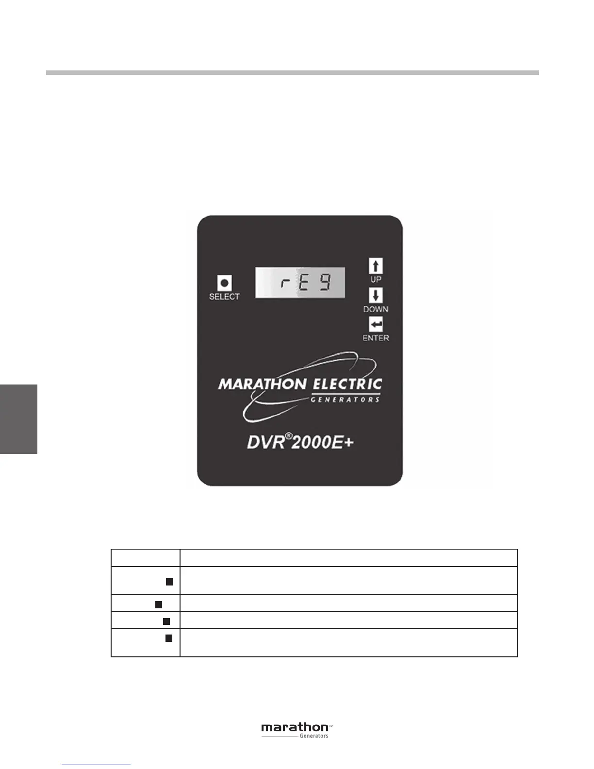
The DVR
®
HMI consists of four buttons and a four-
character LED display as illustrated in Figure 6-1.
The display indicates status conditions and param-
eter settings. Button function descriptions are given
in Table 6-1.
6
Human-Machine Interface (HMI)
Figure 6-1. DVR
®
2000E+ HMI shown
Button Description
SELECT
This button steps the user through a menu list of editable parameters.
It also serves as an escape key in EDIT mode.
UP Thisbuttonincreasesthesettingleveloftheparameterbeingadjusted.
DOWN Thisbuttondecreasesthesettingleveloftheparameterbeingadjusted.
ENTER Thisbuttonstoresthecurrentvalueoftheparameterbeingadjustedand
returns the user to the main menu list.
h
•
i
;
Table 6-1. DVR
®
HMI Button Function Descriptions
GPN046 04-13.indd 34 4/5/13 10:24 AM