62
B
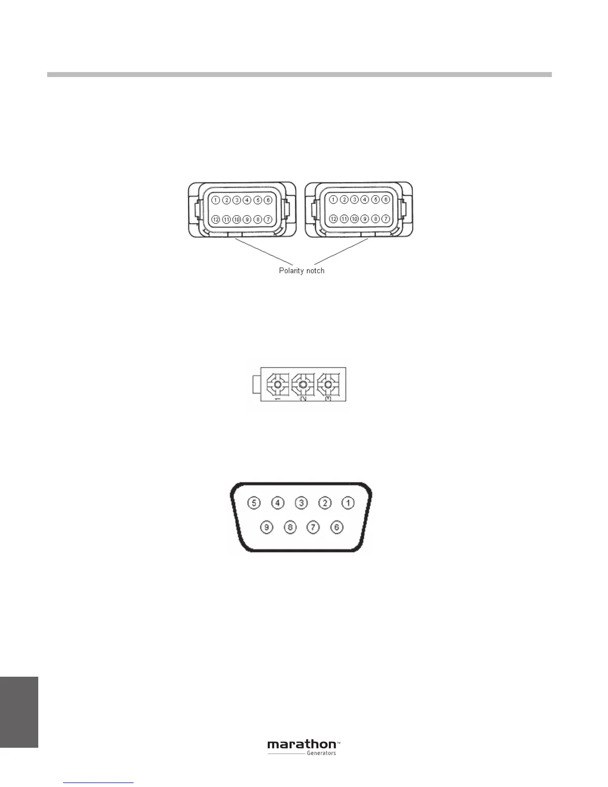
CONNECTOR PIN-OUT FIGURES AND TABLES
The following figures can be used to determine the
pin locations for the pin-integrated connectors used
on the DVR
®
regulator.
Refer to Section 3 - Specifications, for mating con-
nector part numbers.
Appendix B
Figure B-1. System Connectors J2 (left) and J1 (right) Terminal Position
Figure B-2. Connector J3
Figure B-3. RS-232 Communication Port
GPN046 04-13.indd 62 4/5/13 10:24 AM