63
B
Appendix B
The following table should be used when making
connections via quick disconnect terminals to the
regulator.
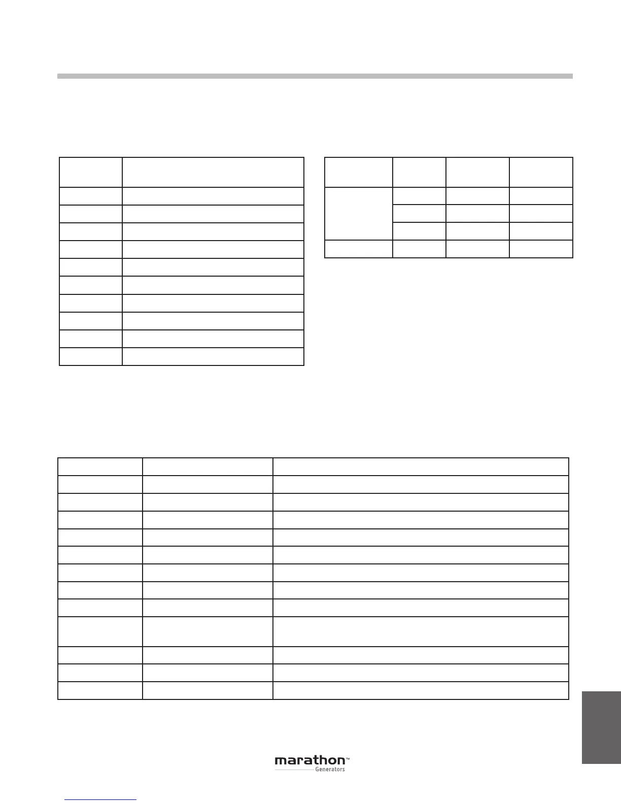
The following table should be used when making
system connections to the regulator.
The following table should be used when making
current transformer connections to the regulator.
Terminal
Name
Description
GND
Protective earth ground
4
PMG – terminal 1
3
PMG – terminal 2 (Fused)
E1
Generator armature – Phase A
E2
Generator armature – Phase B
E3
Generator armature – Phase C
F-
Exciterstatoreld(-)
F+
Exciterstatoreld(+)
CT1
Generator Phase B CT (X1)
CT2
Generator Phase B CT (X2)
Table B-1. Quick Disconnect Terminals
Sensing Phase CT “X1”
Terminal
CT “X2”
Terminal
3-Phase
A J2-1 J2-12
B J2-2 J2-11
C J2-3 J2-10
1-Phase
B CT1 CT2
Table B-2. CT Connection Terminals
Pin Number Name Description
1 AUX IN (+) Auxiliary input positive
2 UP UP contact input (active low)
3 DOWN DOWNcontactinput(activelow)
4 CGND Input common
5 AUX_LOOP Auxiliarycurrentloopjumper
6 CONTACT1 Contact output
7 CONTACT2 Contact output
8 AUX_LOOP Auxiliarycurrentloopjumper
9 VAR/PF_OFF
VAR/PFregulationmodesdisablecontactinput
(EC+ only, active low)
10 DROOP_OFF Droop disable contact input (active low)
11 EXCITATION_OFF Excitation disable contact input (active low)
12 AUX IN (-) Auxiliary input negative
Table B-3. Connector J1 System Connections
GPN046 04-13.indd 63 4/5/13 10:24 AM