64
B
The following table should be used when making
MODBUS communication connections to the
regulator.
The following table should be used when making
CAN communication connections to the regulator.
Appendix B
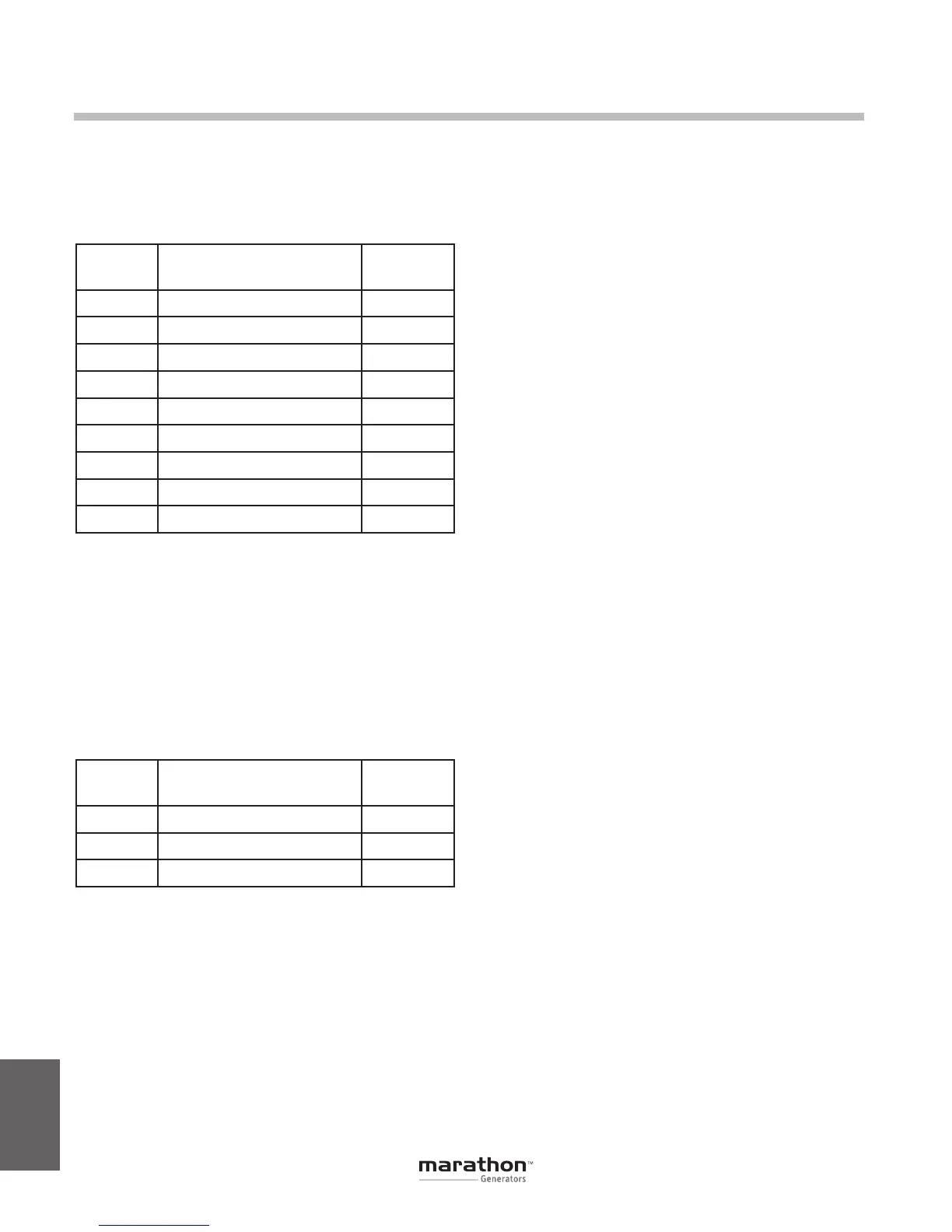
Pin
Number
Function Name
1 N/C
2 Receive Data RXD
3 Transmit Data TXD
4 Data Terminal Ready DTR
5 Signal Ground GND
6 Data Set Ready DSR
7 Ready To Send RTS
8 N/C
9 N/C
Table B-4. RS-232 Communication Port Pin Functions
Pin
Number
Function Name
1 CAN High CAN_H
2 CAN Low CAN_L
3 CAN Ground CAN_GND
Table B-5. Connector J3 System Connections
GPN046 04-13.indd 64 4/5/13 10:24 AM