2-5
Nº32 Reference Preamplifier Basic Operation
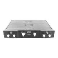
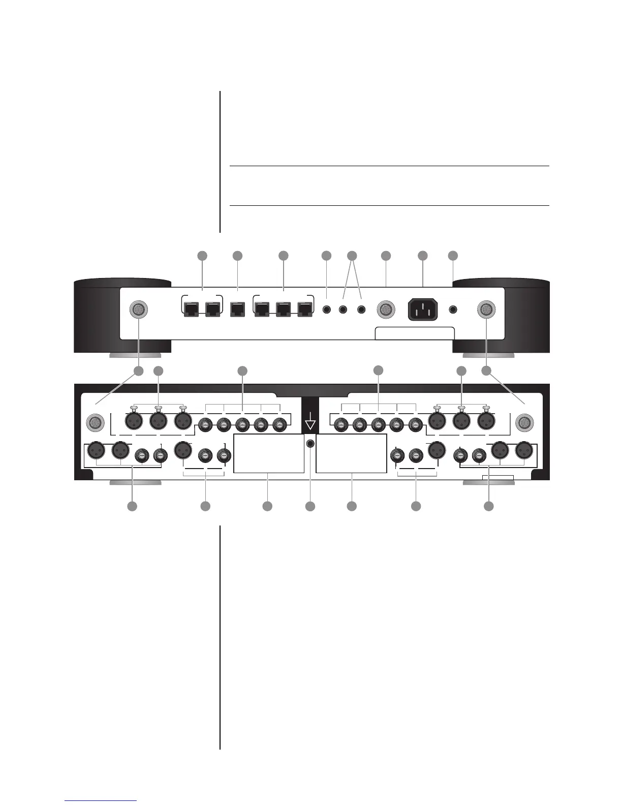
Rear Panel
The numbers in the rear panel illustration shown in Figure 2-2
correspond with the summary list items below.
Note For maximum channel separation, all left and right-channel connectors
are located on opposite sides of the rear panel.
Figure 2-2: N°32 Preamplifier and Controller rear panels.
1. DC power connectors
2. balanced input connectors
3. unbalanced input connectors
4. main output connectors
5. record output connectors
6. phono module access panels
7. phono ground connector
8. control ports
9. RS-232 port
1514
13
DC power
DC power
main outputs
inputs
1
2 3
record outputs
phono
ground
3 2 1
inputs
record outputs main outputs
right channel
DC power
PHASTLink™ compa tible
RS-232
master amplifierslave in
communica tions por ts
ir input trig intrig out
Nº25/S
DC power
Nº32 Ref erence Controller
s/n
ac mains earth
left channel
DC power
8
control p orts
9
10 11
1
1
2 3
4
8
6
5
7
RIGHT CHANNEL
2
3
8 7 6 5 4
LEFT CHANNEL
4
4
MARK LEVINSON REFERENCE
PREAMPLIFIER Nº32
s/n
5
1
2 3
5
1
2 3
6
6
7
12