4-14
Controls and Modes Mark Levinson
Link Connections DO use Link communication ports, such as slave in, slave out, and
amplifier ports. DO NOT use RS-232 ports or other rear panel
connectors.
DO use Link cables, which are available at authorized Mark
Levinson dealers.
DO use constructed Link cables. “Constructing Link Cables” below
for additional information.
Caution! Link connections must be made using Link communication ports
and Link cables. Connections made using other connectors or
cables may damage the Nº32 and other linked components, pos-
sibly voiding the manufacturer’s warranty and/or standard repair
policies.
Constructing Link Cables
Link cables can be constructed using an 8-conductor modular tele-
phone cable with the appropriate plug crimped on each end.
• Use an 8-pin RJ-45 plug to connect digital audio processors,
digital transports, and the Nº32.
• Use a 6-pin RJ-11 plug to connect to power amplifiers. If the
plug on the other end is an RJ-45, do not use the wires from
pins 7 and 8.
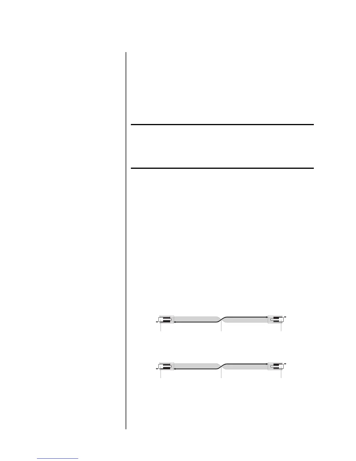
When linking components with constructed Link cables, twist the
cable 180° as shown in Figure 4-1 for a straight-through (pin 1-to-
pin 1) connection.
Figure 4-1: Constructed link cables.
Creating a Slave Chain
Making Link connections creates a slave chain that facilitates
communication among linked components, allowing them to share
Link controls. Table 4-2 on page 4-16 indicates slave chain require-
ments for each component.
Mark Levinson
Digital Transport
Nø32 Reference
Preamplifier
180û Twist
8-Pin RJ-45 Plug (Pin 1)
8-Pin RJ-11 Plug (Pin 1)
Locking Tab Locking Tab
Nø32 Reference
Preamplifier
Mark Levinson
Power Amplifier
180û Twist
8-Pin RJ-11 Plug (Pin 1)
6-Pin RJ-11 Plug (Pin 1)*
Locking Tab Locking Tab