EasyManua.ls Logo

Marksman X6 - HC3: Black 3-Pin Door Lock Harness

Default Icon
27 pages
Print Icon
To Next Page IconTo Next Page
To Previous Page IconTo Previous Page
Loading...
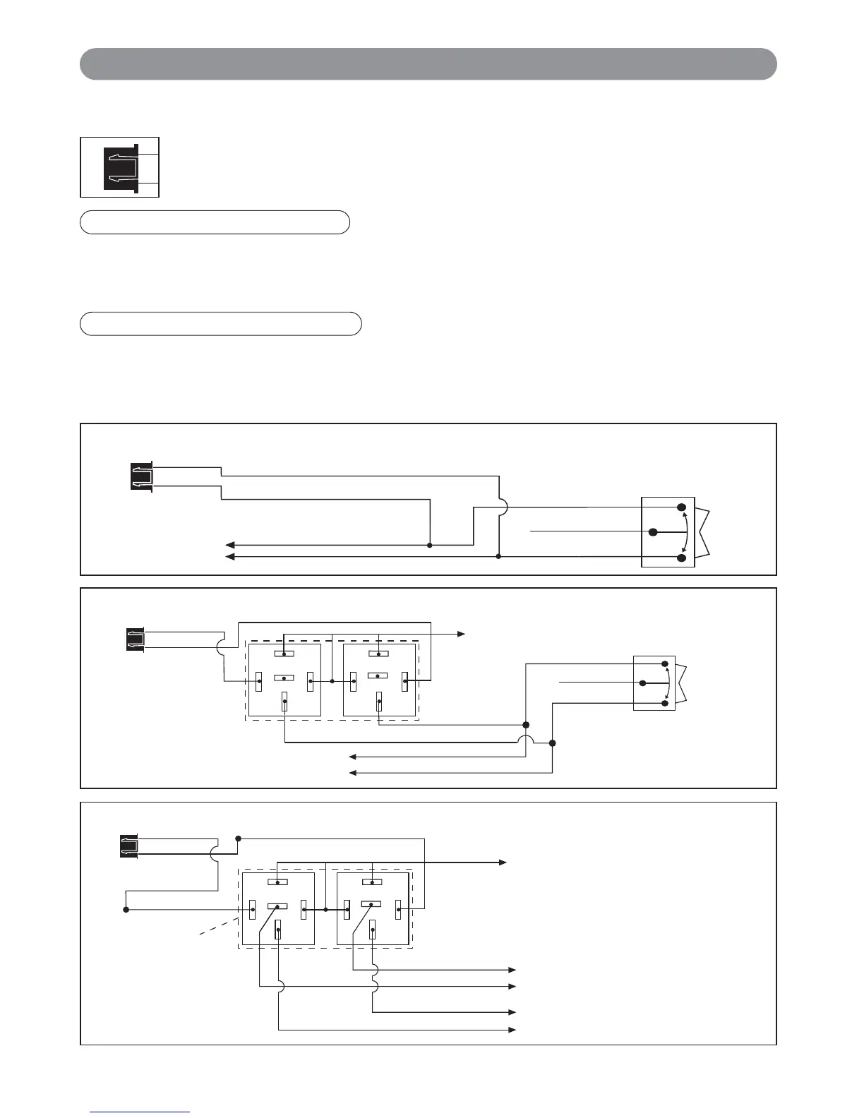
If the door lock control system on the vehicle is (-) type, connect the Blue wire to the unlock wire from the door
lock switch . If the door lock control system on the vehicle is not (-) type, locate the diagram enclosed that
matches your application and follow that diagram.
If the door lock control system on the vehicle is (-) type, connect the Green wire to the lock wire from the door
lock switch . If the door lock control system on the vehicle is not (-) type, locate the diagram enclosed that
matches your application and follow that diagram
Green Wire: (-) Door Lock Control
8
HC3: Black 3-Pin Door Lock Harness
Wiring (continued)
Blue Wire: (-) Door Lock Control
3 Wire Ground Trigger Door Lock System
(
-
) Lock Out
Ground Input
(
-
) Unlock Out
To Door Lock
Control Relays
Lock Control
Switch
Blue Wire: Connect to Unlock
Green Wire: Connect to Lock
Black 3-Pin
Mini Connector
3 Wire Positive Door Locking Systems
87
87A
85
86
30
87
87A
85
86
30
To +12 Volts
(Battery +)
Black 3-Pin
Mini Connector
Green Wire
Blue Wire
Note: ALA-DL1 relay
pack can be used
(+) Lock Out
+12 Volts Input
(+) Unlock Out
Lock Control
Switch
To Factory Door
Lock SYstem
5 Wire Ground at Rest Door Locking Systems
87
87A
85
86
30
87
87A
85
86
30
To +12 Volts
(Battery +)
To Power
Lock Switch
To Power
Lock Motors
White Wire: Lock
Brown Wire: Unlock
Green Wire: Lock
Blue Wire: Unlock
Violet Wire
ALA-DL1
Relay Pack
Red Wire: Lock
Black Wire: Unlock
Black 3-Pin
Mini Connector
Green Wire
Blue Wire
Note:
Orange wire from ALA-DL1
must be connected to +12V
X6-IM.qxp 9/12/2008 1:50 PM Page 8

Related product manuals