13
Wiring (continued)
HC4: White 9-Pin Accessory Harness (continued)
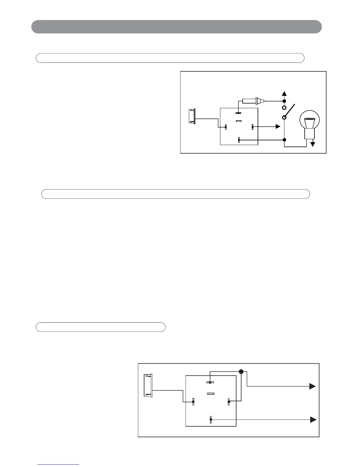
Dome Light Control Output :
This wire becomes grounded when the system is
unlocked. The current capacity of this wire is
200mA. This wire can control the operation of the
interior lights. Use of optional relay as shown is
recommended. Upon unlocking, the interior lights
will remain on for 30 seconds.
Ground Output During Crank Option: (See “Alarm Feature Programming”):
This wire can be used to control another device as needed when the remote start is cranking the engine.
This wire will supply a constant ground while the engine is cranking.
Driver’s Door Priority 2nd Unlock Output:
By default the Light Blue wire provides a second (-) unlock output to unlock the passenger’s doors. Follow the
diagrams on pages 8-10 for proper connection.
Factory Security Disarm Output:
The Light Blue wire can be programmed to provide a (-) pulse output every time the X6 is unlocked. This
connection can be used to disarm the vehicles factory security system at the same time the X6 is unlocked.
See Alarm Feature Programming (Group 1), page 18.
Start Status Output:
The Light Blue wire can be programmed to provide a constant (-) output during the time that the vehicles
engine is running under the control of the X6. In this configuration, the Light Blue wire can be used as sensor
bypass control. Connect a relay to the sensor power wire and use the Light Blue wire to trigger the relay. See
Alarm Feature Programming (Group 1), page 18.
Some newer vehicles use a third ignition wire which is required to start and keep the vehicle’s engine running. The
Pink wire provides a 200mA (-) ground output that becomes active 4 seconds before the remote start unit initializes.
This wire remains grounded while the
engine is running. This is a low
current output wire and will require a
30a/40a relay (not supplied) for
correct operation. Wire the relay as
shown.
Note: This wire can an also be used
to control an ignition immobilizer
bypass module.
87
87a
86
85
30
White
Wire
White
9-Pin Mini
Connector
+12V
Courtesy
Light
Door
Switch
Fuse
+12 Volts or Ground Depending
on Vehicle Requirement
White Wire : (-) 200mA Programmable Output (Dome Light Supervision Default Setting)
Light Blue Wire : (-) 200mA Programmable Output (2nd Unlock Output Default Setting)
Pink Wire : (-) 200mA Ignition 3 Output
87
87a
86
85
30
Pink
Wire
+12 V Constant
Fused 25A Capable
Ignition 3 Wire from
Ignition Key Switch
White
9-Pin Mini
Connector
X6-IM.qxp 9/12/2008 1:50 PM Page 13