- User Manual
3. USING THE E32A SSR INTERFACE
3.1 Enabling the output: PROBE OUTPUT signal
The output can be enabled using the ENABLE P.O. input signal. This signal enables the user to control the
P.O. output (by selecting the TRUE/FALSE logic level) even when the measurement cycle is not running.
Enable P.O. = TRUE sets the P.O. signal to TRUE when the measurement cycle is not running, otherwise it
will always set it to FALSE. Therefore it is best to use one of the two following configurations:
P.O. = TRUE even when the measurement cycle is not running.
Enable P.O. = ARO
P.O. = TRUE only when the Touch probe is deflected during the
The MIDA SET, Electrical MIDA TOOL EYE, and Manual MIDA TOOL EYE arm operating cycle diagrams,
in the two different configurations, are illustrated below.
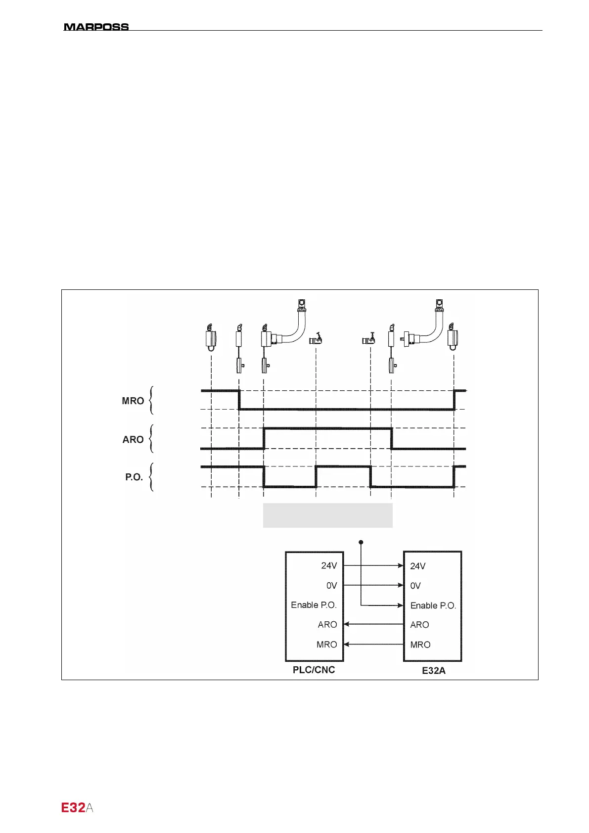
3.1.1 MIDA SET arm cycle diagram (Enable P.O. =VTRUE)
Figure 3-1. Enable output MODE 1 – operating cycle diagram.
Probe enabled
FALSE
FALSE
TRUE
TRUE
TRUE