- User Manual
5. DIAGNOSTICS
N.B.
Any system faults or malfunctions are indicated by the E32A interface
5.1 E32A: Alarms
Whenever an alarm condition is detected:
• The arm connected to E32A stops moving; the red LED L2 on the equipment case is illuminated;
• the No Fault output signal is set to low logic level; this line can be tested to detect the absence of
alarms;
• the yellow LED L2 indicates the alarm conditions by generating a pulse sequence, see para. 5.1.1
“Alarm signals”.
E32A waits until the fault condition generating the alarm has been resolved, and it receives a
command that is consistent with its operating mode.
• The alarm condition is displayed until the alarm is reset.
• The alarm display is cancelled as soon as normal conditions are restored.
5.1.1 Alarm signals
When an alarm is detected, the yellow LED describes the alarm condition by flashing in a pre-established
sequence at two second intervals. The number of flashes in each sequence identifies the alarm, in
accordance with the table below.
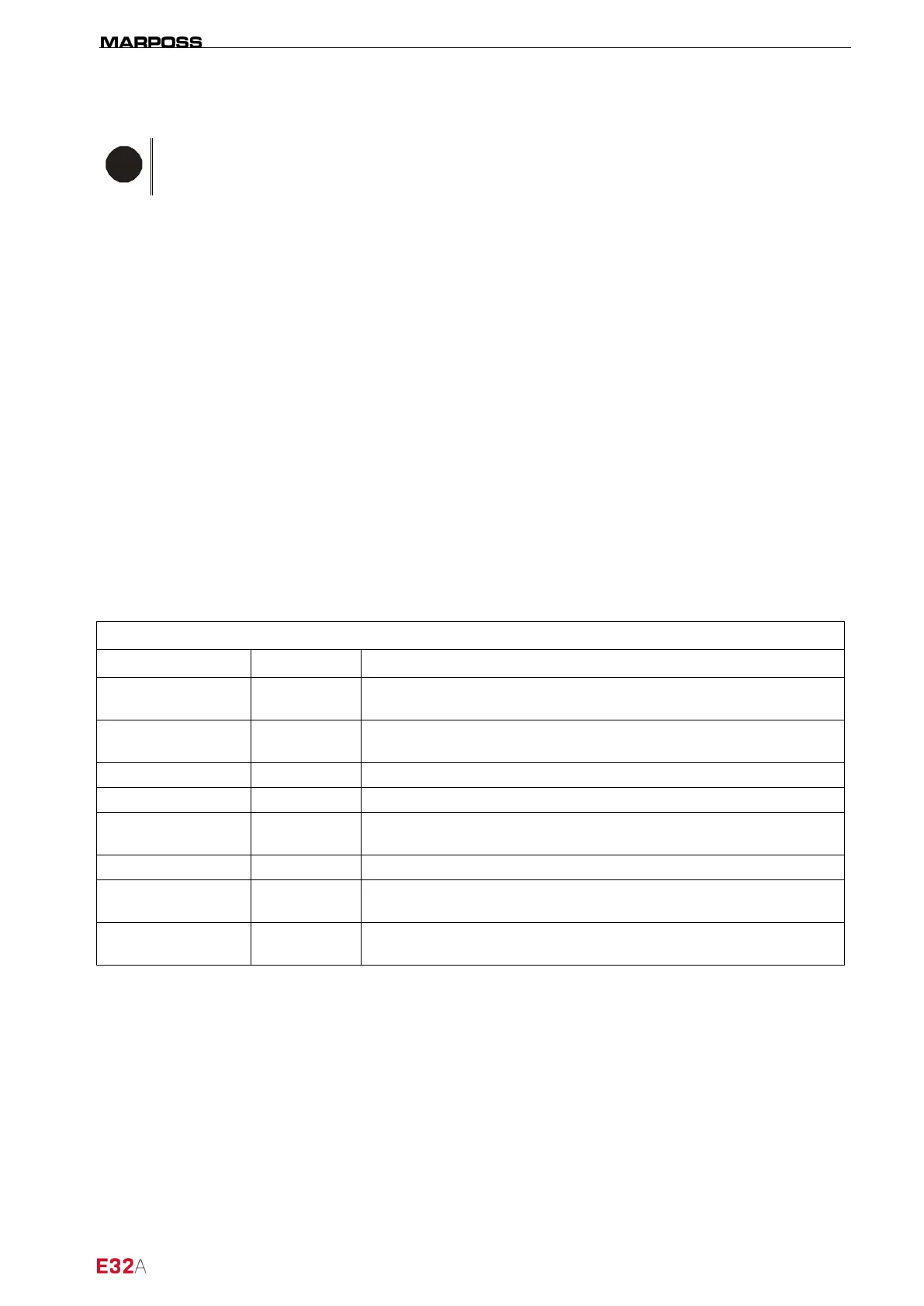
Table 5-1. Alarm type indication.
Event Nr. of pulses Meaning
TIMEOUT_ERROR 2
The electrical arm movement was not completed within the
maximum time permitted
INVALID
UP_DOWN_START
3
Request to move the electrical arm simultaneously to the
measurement position (ARC) and the rest position (MRC)
EXT_IO_FAULT 4 Short circuit to earth in the output to PLC logic circuits.
OPEN_LOAD 5 The driver detects an open circuit at the motor connection terminals.
SHORT_TO_VS
OR_LOAD
6 The driver detects a short circuit at the motor connection terminals or
one of the terminals appears to be connected to the power supply.
SHORT_TO_GND 7 The driver detects at least one terminal connected to earth.
TEMPERATURE_
WARNING
8 Motor driver over temperature.
POWER_SUPPLY_
FAIL
9 The motor driver power supply is insufficient.