- User Manual
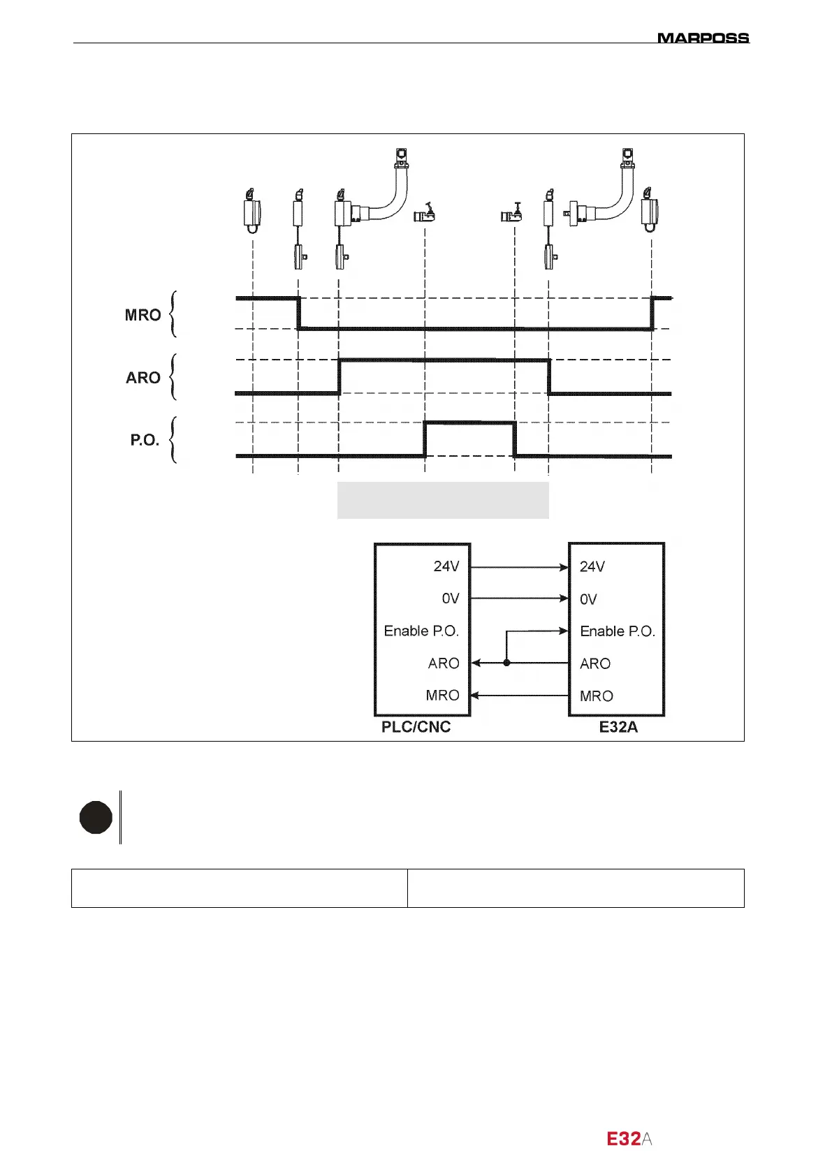
3.1.2 Alternative MIDA SET arm cycle diagram (Enable P.O. =ARO)
Figure 3-2. Enable output MODE 2 – operating cycle diagram.
N.B.
Once the signal logic has been verified (TRUE/FALSE), check on the machine whether it is
necessary to work in SOURCE or SINK mode.
By default, the interface is set to SOURCE mode, to change this mode, see paragraph “4.4 Selecting
SINK/SOURCE operating mode” on page 19.
Probe enabled
(measurement cycle)
FALSE
FALSE
FALSE
TRUE
TRUE
TRUE
= Arm ready for measurement
= Arm at rest
= PROBE OUTPUT