Marquette Hellige GmbH MicroSmart V 2.xx Page 12
Servicing Instructions 227 470 35 B - 97.12
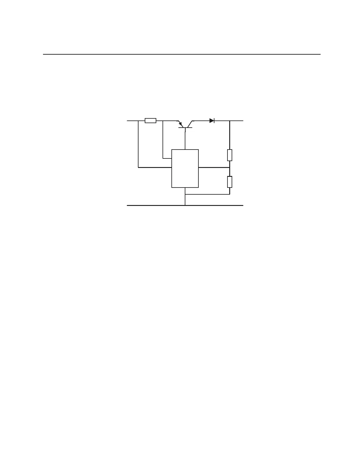
Battery charge
Voltage query
charge
control
Uin
GND GND
Uout
Battery charge
Current query
X501
T500
The battery is charged by means of a special charging IC (UC3906) for lead batteries. The circuitry
monitors the charging current and the charge voltage. The charging IC has the same "temperature
coefficient" as a lead battery, with the effect that the battery charge is optimized over the specified
temperature range. The circuit operates as a "DUAL LEVEL FLOAT CHARGER", with three
distinct charging states:
- high current bulk charge state
- over-charge state
- float state
A charging cycle begins with "high current bulk charge state". In this state the battery is charged
with a constant current ( I
max
) while the battery voltage is monitored. The "over-charge state" sets
in as soon as a certain voltage value ( U
12
) is reached. In this state the battery voltage is kept at
a certain value ( U
OC
), while the charging current is monitored. If the charging current drops to
a certain value ( I
OC
), the "float state" sets in. At this point in time the battery capacity has risen
to almost 100%. In the "float state" the battery voltage is regulated to a precise value ( U
F
).
The following values for voltage and current are selected when charging the 12V lead battery:
I
max
= 250mA
U
12
= 13.5V
U
OC
= 14.2V
I
OC
= 25mA
U
F
= 13.7V