Marquette Hellige GmbH MicroSmart V 2.xx Page 32
Servicing Instructions 227 470 35 B - 97.12
3.4.4 Interface, motor
Plug designation: AC/
Plug connector 6-pin, upright (180 °), reverse voltage protection implemented mechanically.
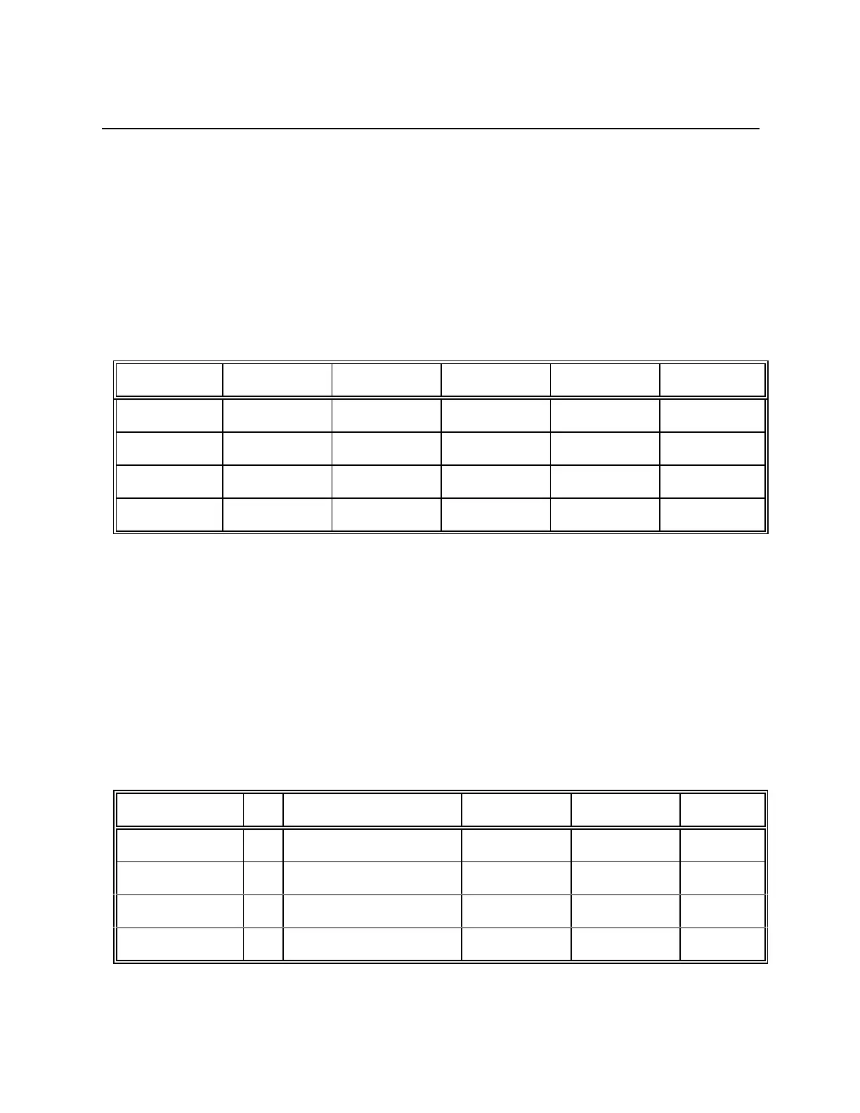
The function of the individual pins is shown in the following table. The definition in terms of
input/output is as seen from the PCB MicroSmart.
Signal name I/O Meaning Level Polarity Pin No.
Q11 O Field coil 1 +24V --- 1
Q12 O Field coil 1 +24V --- 2
Q21 O Field coil 2 +24V --- 3
Q22 O Field coil 2 +24V --- 4
3.4.5 Interface, photoelectric barrier
Pin designation: AB/
Zero power flat membrane connector 4-pin, upright (180 °), reverse voltage protection
implemented mechanically.
The function of the individual pins is shown in the following table. The definition in terms of
input/output is as seen from the PCB MicroSmart.
Signal name I/O Bedeutung Level Polarity Pin No.
SENSOR_TR I Collector Phototrans. 0-5V --- 1
SENSOR_GND --- Ground 0V --- 2
SENSOR_LED O Anode LED 2.5V --- 3
--- --- Free --- --- 4