Marquette Hellige GmbH MicroSmart V 2.xx Page 57
Servicing Instructions 227 470 35 B - 97.12
Test has failed if the measured values are greater than:
N.C. S.F.C
100 µA 500 µA
300 µA (U.L. requirements)
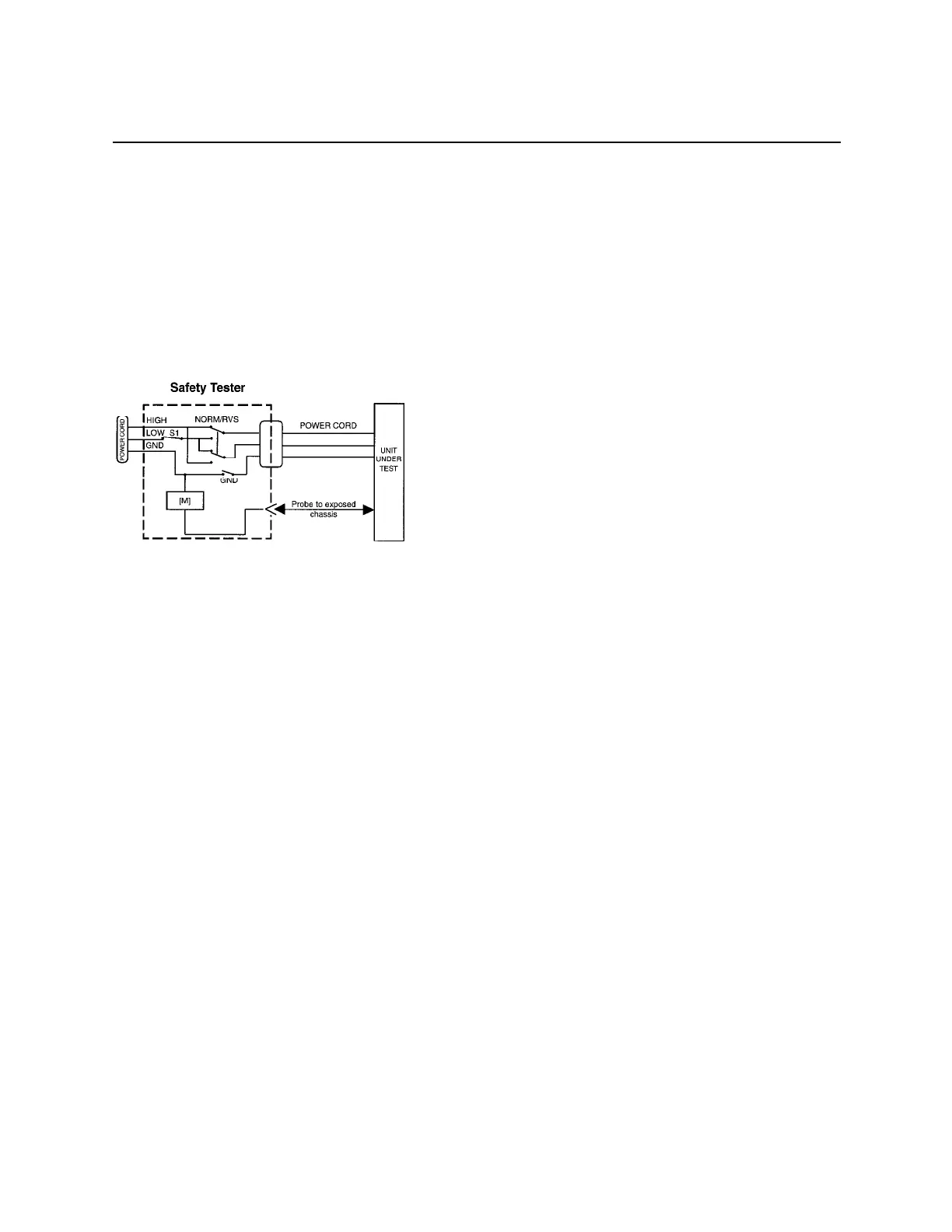
Electrical diagram for Enclosure Leakage Current Test
8.2.5 Patient Leakage Current Test
This test performs a leakage current test under single fault conditions (S.F.C.) dependent of
domestic power outlet with 115 or 230 V AC as source into the floating inputs.
In any case, the leakage current is measured from Input Jack, of unit under test, to ground.
For testing the ECG input, a patient cable, with all leads connected together, is used.
Connect the unit under test to your Safety Tester.
- Referring to the electrical diagram, measurements have to be done under following
conditions
* Polarity switch NORM and RVS
* GND switch GND closed
*S1 closed
Test has failed if the measured values are greater than 50 µA