Marquette Hellige GmbH MicroSmart V 2.xx Page 56
Servicing Instructions 227 470 35 B - 97.12
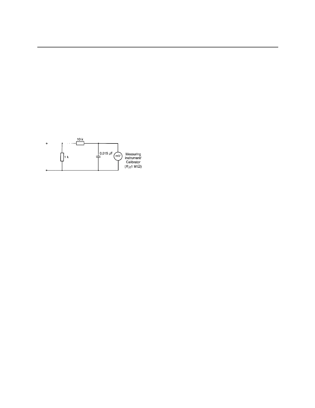
8.2.3 Measuring of leakage current
To proceed the suggested measurements, the unit under test has to be separated from any
interconnection to a system. If the unit is part of a system, extended tests according IEC 601-1-1
have to be performed. The following diagram shows the
needed Measuring Circuit [M] for leakage current. The reading in mV corresponds to uA
(leakage current). The Safety Testers generally work with this Measuring Circuit [M] and the
displayed values are already converted to leakage current.
8.2.4 Enclosure Leakage Current Test
This test is performed to measure leakage current from chassis to ground during normal
conditions (N.C.) and single fault conditions (S.F.C.).
In any case, the leakage current is measured from any exposed conductive parts to ground, the
unit under test has to be switched on and off.
Connect the unit under test to your Safety Tester.
- During normal conditions (N.C.), referring to the electrical diagram, measurements have
to be done under following conditions:
* Polarity switch Norm and RVS
* GND switch GND closed
* S1 closed and open
- During single fault conditions (S.F.C.), referring to the electrical diagram, the
measurements have to be done under following conditions:
* Polarity switch NORM and RVS
* GND switch GND open
*S1 closed