Marquette Hellige GmbH MicroSmart V 2.xx Page 30
Servicing Instructions 227 470 35 B - 97.12
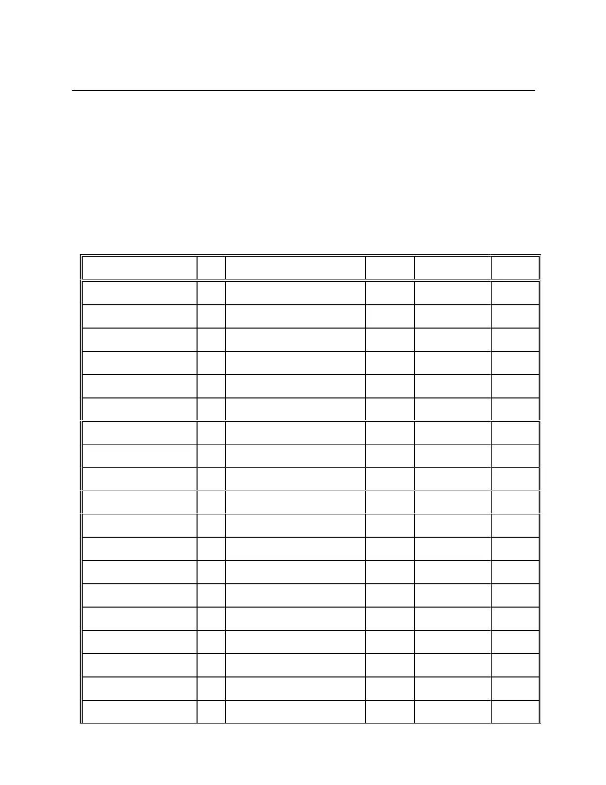
3.4.3 Interface, thermal array
Plug designation: AA/
Socket connector 2 x 15-pin upright (180 °), Caution! No reverse voltage protection!
The function of the individual pins is shown in the following table. The definition in terms of
input/output is as seen from the PCB MicroSmart.
Signal name I/O Meaning Level Polarity Pin No.
V
H
--- +24V +24V --- 1
V
H
--- +24V +24V --- 2
GND --- +24V 0V --- 3
V
H
--- Ground +24V --- 4
GND --- Ground 0V --- 5
GND --- Ground 0V 6
DATA IN 1 I Data input 1 TTL --- 7
DATA OUT 1 O Data input 1 TTL --- 8
DATA IN 1 I Data input 2 TTL --- 9
DATA OUT 2 O Data output 2 TTL --- 10
STROBE 1 I Strobe 1 TTL active high 11
STROBE 2 I Strobe 2 TTL active high 12
THERMISTOR 1 --- NTC resistor --- --- 13
LATCH I Array latch TTL active high 14
VDD Logic Supply +5V --- 15
NC --- --- --- --- 16
THERMISTOR 2 --- NTC resistor --- --- 17
CLOCK I Array clock TTL L->H 18
STROBE 3 I Strobe 3 TTL active high 19