Marquette Hellige GmbH MicroSmart V 2.xx Page 33
Servicing Instructions 227 470 35 B - 97.12
3.4.6 Interface, keyboard
Plug designation: AS/
Zero force flat membrane connector 18-pin, upright (180 °), reverse voltage protection
implemented mechanically.
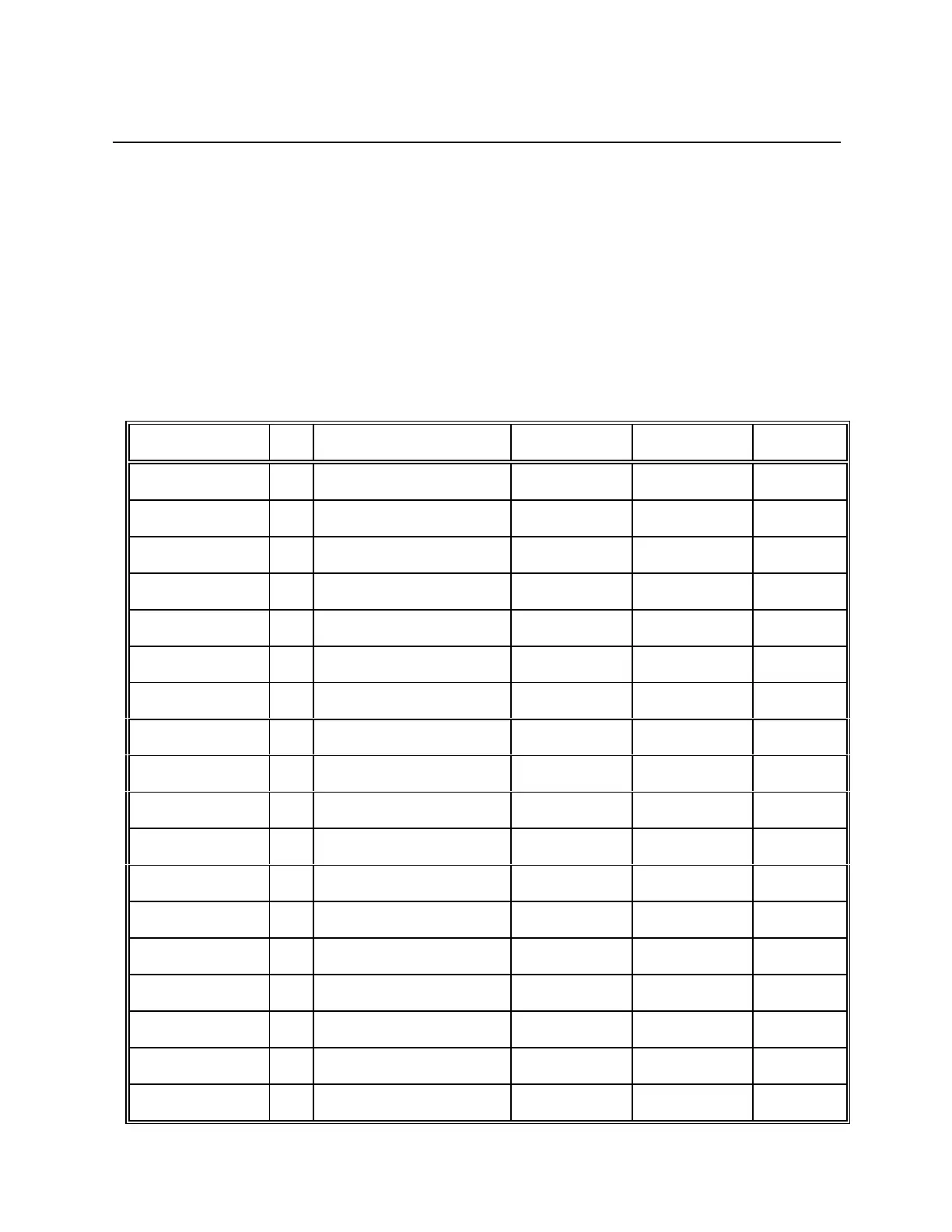
The function of the individual pins is shown in the following table. The definition in terms of
input/output is as seen from the PCB MicroSmart.
Signal name I/O Meaning Level Polarity Pin No.
LED_LOBAT O Anode battery LED +5V --- 1
LED_NETZ O Anode system LED +15V --- 2
GND O Ground GND --- 3
COLUMN4 O Matrix column 4 +5V --- 4
COLUMN3 O Matrix column 3 +5V --- 5
ROW4 I Matrix row 4 +5V --- 6
COLUMN2 O Matrix column 2 +5V --- 7
COLUMN1 O Matrix column 1 +5V --- 8
COLUMN5 O Matrix column 5 +5V --- 9
ROW5 I Matrix row 5 +5V --- 10
ROW3 I Matrix row 3 +5V --- 11
ROW2 I Matrix row 2 +5V --- 12
ROW1 I Matrix row 1 +5V --- 13
ON_OFF O Key ON/OFF +15V --- 14
GND O Ground GND --- 15
LED_STOP O Anode STOP LED +5V --- 16
LED_START O Anode START LED +5V --- 17
GND O Ground GND --- 18