Marquette Hellige GmbH MicroSmart V 2.xx Page 29
Servicing Instructions 227 470 35 B - 97.12
3.4.2 Interface, display
Plug designation: AE/
Socket connector 1 x 14-pin, upright (180 °), reverse voltage protection implemented mechanically.
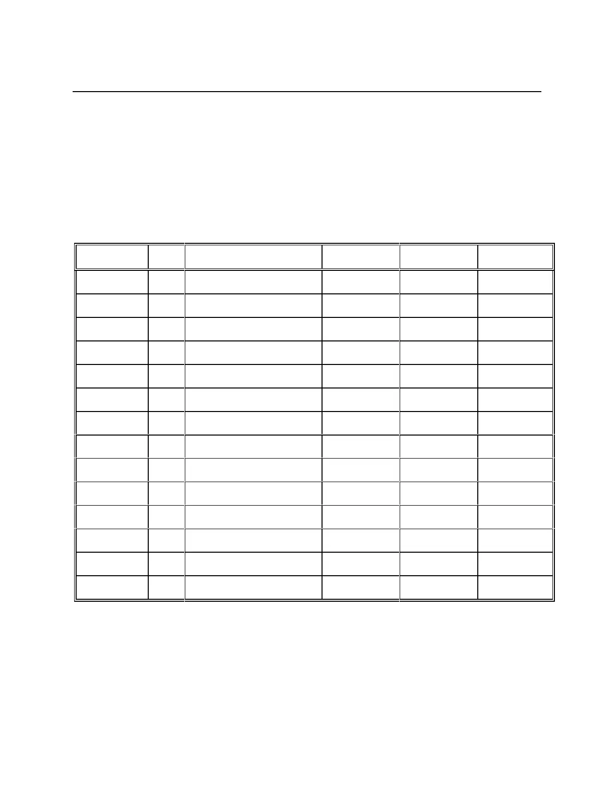
The function of the individual pins is shown in the following table. The definition in terms of
input/output is as seen from the PCB MicroSmart.
Signal name I/O Meaning Level Polarity Pin No.
Vss --- Ground 0V --- 1
VDD --- Supply +5V --- 2
V0 --- Contrast voltage 0-5V --- 3
RS O Register select TTL 4
R/W O Read/Write TTL --- 5
E O Enable TTL active-high 6
DB8 I/O Data TTL --- 7
DB9 I/O Data TTL --- 8
DB10 I/O Data TTL --- 9
DB11 I/O Data TTL --- 10
DB12 I/O Data TTL --- 11
DB13 I/O Data TTL --- 12
DB14 I/O Data TTL --- 13
DB15 I/O Data TTL --- 14